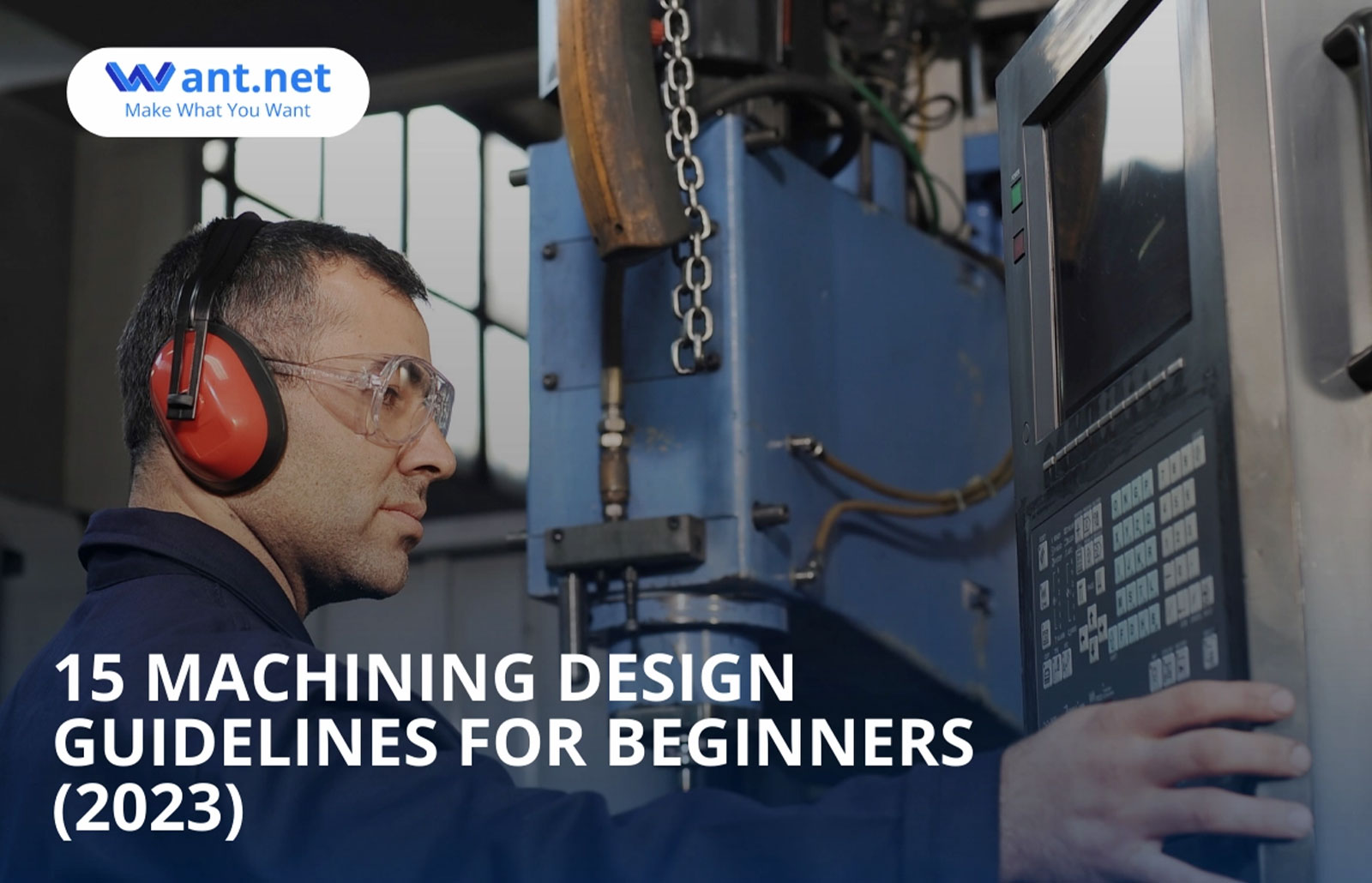
CNC machining is a flexible production method that can manufacture a range of products with great precision and accuracy. High-precision, complex parts are manufactured with this method in a variety of industries, including electronics, aerospace, automotive, and healthcare.
China Online CNC Machining Service
Despite all of its features, it is necessary to strictly adhere to CNC machining design standards in order to ensure that components are manufactured to the highest quality standards.
You can create parts that satisfy required specifications and production requirements, guarantee excellent quality and accuracy, and more by following the accepted CNC machining design guide. Designing parts for CNC machining requires the skills and strength of the abilities and restrictions of the equipment. This article discusses critical design criteria and guidelines for CNC machined parts to get the best results.
What Is A CNC Machine?
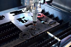
CNC machining is a subtractive manufacturing technique that includes both milling and turning. This technique makes direct contact with a solid block of material to remove material from it using a variety of cutting tools.
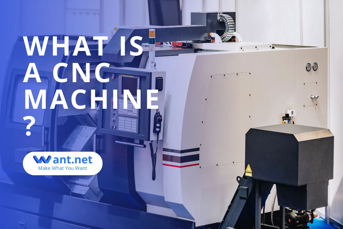
A CAD file is used in the process, which is a computerized manufacturing technology that produces products with great physical features. CNC machining is suitable for both low- and medium-volume production due to its high level of automation.
Basic Guidelines for CNC Machining Design
Here are some general guidelines to follow while designing for CNC machining.
Considerations for CNC Design
- Create components that are simple to machine with large-diameter tools to enable quick processing without requiring specialized equipment;
- Cavities shouldn’t be deeper than four times their breadth because doing so makes machining slightly more complex;
- While creating your design, consider the primary direction your machine may move as well as its typical number of axes to avoid problems;
- To prevent errors in the engraved text, never use sizes smaller than 20 points.
What Are Design Restrictions for CNC Machining?

It’s true that CNC machining is flexible, but not every design is practical. In order to ensure smooth machining, you must be aware of the limitations and restrictions. The two main restrictions for CNC design are;
Tool Geometry
The cutting length of the majority of CNC cutting tools is limited. Moreover, they are all cylindrical in shape and geometry. These cutting tools transmit their cylindrical geometry to the workpiece when removing materials from it. Due to this, the interior corners of a workpiece have a constant radius, regardless of the size of the cutting tool.
Tool Access
When handling a workpiece with a high depth-to-width ratio, access to tools becomes a major issue. This is a concern because CNC machines use cutting tools that are pushed to the workpiece from above to cut.
What Are CNC Machining Design Guidelines?
There are no widely accepted standards in the field of CNC machining. This is primarily due to the constant evolution of both the industry and the technology used. Even though, following a few guiding principles and recommendations would help to maintain the high caliber of your designs. These recommendations consist of,
Internal Edges
For creating inner edges, the vertical corner radius must be at least one-third of the cavity depth. If you use the recommended corner radii, you can use a diameter tool with the recommended cavity depth.
A higher-quality surface finish can be achieved by cutting along a circular path rather than a 90-degree angle when corner radii are slightly more than the recommended value. If you need a 90-degree angle instead, it is recommended to use a T-bone undercut instead of reducing the corner radius.
Holes
Machine operators may use drill bits and end mill tools to make holes. The dimension of the holes in your CNC machine design should ideally be determined by conventional drill bit sizes, calculated in either metric or imperial units.
Theoretically, any dimension more than one millimeter is possible. Reamers and boring tools are used by machine operators to finish holes that must follow strict specifications. Regarding holes smaller than 20 millimeters that need to be extremely accurate, it is best to use a standard diameter.
The maximum intended depth for every hole when designing for CNC machining is four times the actual diameter, but 40 times this number is possible. Usually, the actual diameter is 10 times the ratio.
Threads
M2 is the smallest thread size that can be used for creating products for CNC machining, but M6 or larger is typically preferable. Machine operators can reduce the risk of tap damage by utilizing CNC threading machines to create threads as short as M6.
The thread length must be at least 1.5 times the actual diameter and should ideally be three times the normal length. An unthreaded length 1.5 times the recommended diameter must be added at the bottom of the hole for any thread smaller than M6. It is best to thread larger than M6 threads through the whole length of the hole.
Cavities and Pockets
The suggested cavity depth for any design is 4 times its breadth since end mill tools are limited in how long they can cut. More chip evacuation, tool deflection, and vibration would be the effects of a lower depth-to-width ratio.
Do you need deeper depths for your CNC design? One solution is to use a changing cavity depth and a specialized instrument to handle this problem.
Guidelines for Using CNC Machines While Creating Components
A high-quality item or product is ensured by following best practices and being aware of the fundamentals of CNC machining. Following are some best practices to remember while designing parts for CNC machining, based on the type of machining.
CNC Milling Design
CNC milling is a type of machining where raw materials are quickly stripped of material using circular cutters to produce the required form. The milling machines are available in a wide variety of designs, from 3-axis to 12-axis.
Frequently Used Cutting Tools
When developing concepts for CNC part design, keep in mind the various tools often used for CNC milling, like end mill cutters. Cost and lead time will be significantly reduced if the specific set and geometry can be produced using conventional tools.
When developing your design, keep in mind tool standard sizes as well, since a CNC machine design with a radius lower than the standard will result in design difficulties and cost.
Avoid Internal Sharp Corners
Sharp corners cannot be produced using a milling tool. The round cutting tool used in this case is the reason. Your corners must have radii greater than the cutter used to cut them if you plan to use a CNC mill. The cutting tool’s diameter should preferably be double the radius it is creating.
A sloped or drafted surface must also meet a vertical wall or sharp edge; this is when fillets are required. An end mill with a square or ball shape always leaves material between the wall and the surface below unless the surface is level with the tool.
Deep Narrow Slots Should Be Avoided
Poor surface quality is often the result of the vibration and deflection that long tools experience. As a result, the final depth of cut of an endmill shouldn’t exceed more than 15 times its diameter when cutting plastic, 10 times its diameter when cutting aluminum, and 5 times its diameter when cutting steel.
For example, the depth of a slot made with a 0.5′′ end mill that is 0.55′′ broad on a machined steel part should not exceed 2.75′′. Any internal radii should be greater than 0.25′′ since the internal fillet radius—the previous point—also depends on the tool geometry in this situation.
Design for CNC Turning
CNC turning is a machining process that uses a lathe to make objects with axial symmetry and cylindrical geometry. The workpiece is held in place on a spinning grip while being cut into the appropriate shape by the cutting tool. Tighter tolerances and a superior surface polish are the results of this machining technique.
Some Guidelines for Creating a CNC Cutting Design Using a Turning Machine
Avoid Internal and External Sharp Corners
Sharp exterior or interior corners should be avoided when planning for CNC machining. One way to make sure the tool doesn’t run up a larger surface is to give the internal corner a radius. Slanting a steep sidewall slightly is another method for avoiding sharp inner corners. It could be less complicated to produce outlines with a simple lathe-cutting tool because fewer steps are required.
Avoid Long and Thin Parts
Long and thin-turned pieces should not be used since they’re more likely to rotate irregularly and clatter against the tool. Try to provide space for a center drill on the free end when manufacturing long components, and use a center to keep the part spinning correctly. In addition, keep the length-to-diameter ratio at 8:1 or less.
Avoid using thin walls.
Excessive material removal, such as milling, can put extra stress on the component. Walls that are too thin will lose stiffness as well. Yet, narrow walls make it difficult to maintain tight tolerances. For this reason, it’s recommended that you maintain the wall thickness of turned parts in your model for CNC machining above 0.02 inches.
Design for Drilling
This term refers to actions that involve making holes in workpieces. Tools used in this process have a conical tip that enables them to penetrate materials deeply while being machined.
When creating a design for CNC drilling, consider the following CNC guidelines.
Proper hole depth
Never drill more than 12 times deeper than the closest bit diameter. This is because long drill bits lose rigidity and the ability to keep a tight tolerance, and they’re more likely to break. If you need to dig deeper, you should also think about making the hole diameter larger.
On the other hand, drilling from both sides of the part is an additional option if a deep hole is needed. Remember that the need for a separate machining setup will delay the manufacturing process and increase the cost.
Avoid using Partial Holes
Partial holes should be avoided as there is a high possibility that the tip will wander. However, if only a piece of the hole is required, put the drill axis on the material so that the part will support the majority of the hole.
Conclusion
Thus, you just learned a comprehensive overview of designing for CNC machining, which is a debatable topic. Everyone has different standards and perspectives, though. I truly hope you have learned something.