Introduction to CNC Machining and the Importance of Technical Drawings
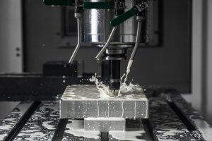
Computer Numerical Control (CNC) machining has become a keystone in modern manufacturing due to its precision, high-speed performance, and automated functionality. It is an important tool that allows for precise manipulation and shaping of materials such as metal, plastic, and wood. The success of each production run heavily depends on the accuracy of the technical drawings used.
Technical drawings are essential for CNC machining as they serve as the blueprint for the operation. These not only depict the physical dimensions and overall visualization of the finished product but also specify crucial information including material type and surface finishes. Thus, developing a comprehensive and precise technical drawing is paramount to ensure complete alignment between the intended design and the final product produced by the CNC machine. Following are some key applications of technical drawings:
- Ensuring exact replication of designs during mass production runs.
- Navigating complex milling processes via thorough elaboration of part geometry details.
- Mitigating risks of production errors through clear dimensional constraints and specifications.
Understanding Technical Drawings
A technical drawing is a visual depiction of an object, concept or design that provides detailed specifications and transmits critical information. They’re essential for producing precision-engineered parts by CNC machining. These drawings incorporate fundamental elements such as lines – which represent different things including visible edges, hidden features or center lines – and symbols, acting as the universal language used to communicate between product designers and manufacturing engineers.
Several common terms come into play in technical drawings. “Tolerance” refers to the allowable variation from the given dimension, making sure the part fits suitably in its intended assembly. The “dimension,” on the other hand, indicates the size or position of a feature. This could include length, diameter, angle or radius. One might encounter ‘
- ‘Scale’, denoting the relation between the actual size of the component and its rendered size in the drawing.
- ‘Section Views’ which present cut-away depictions permitting visibility of internal features.
- ‘Auxiliary Views’ illustrating inclined faces in true size and shape.
All these components are integral to accurately interpreting technical drawings, pivotal for successful production via CNC machining, ensuring accuracy, precision, and efficiency when turning a vision into a tangible item.
Steps to Prepare a Technical Drawing for CNC Machining
The first step in preparing a technical drawing for CNC machining is the conceptualization phase. This process begins with turning an abstract idea into a concrete, visual representation suitable for manufacturing. Initially, your concept might be as simple as a rough sketch or a mental image. To facilitate this transition from idea to a tangible form, CAD (Computer-Aided Design) software can be extremely instrumental due to its ability to create precise and detailed 3D models. The thoroughness of your design at this stage will largely determine the success of the subsequent steps involving drafting and detailing.
- Drafting: Once the model has been created, the next step involves generating a 2D projection of the 3D model, also known as drafting. These drafts serve as a sort of blueprint that the machines use to manufacture your components.
- Detailing: After the drafts are generated, you proceed to add details such as dimensions, tolerances, material specifications and other essential production notes.
Throughout these stages, it is pivotal to consistently review and verify each component and their corresponding functions against the original requirements. With these meticulous preparations, you would have successfully translated your initial concept into a technically sound blueprint ready for CNC machining.
Incorporating CNC Machining Requirements into Your Drawing:
- A technical drawing for CNC machining should include critical features/dimensions of a part, tolerances, indication of threads, finishing preferences, and construction lines.
- Files can be submitted to an on-demand manufacturing service like RapidDirect by uploading them to a web platform, such as IGES or STEP format, to generate a quote for the machining project.
- CAD files should be prepared for CNC machining by converting them into a format recognizable by the CNC machine, such as STEP format.
- Common design guidelines for CNC machining include avoiding non-planar and draft angle surfaces, increasing the size of internal fillets, and adding undercuts to sharp corners.
- Considerations for creating text or lettering in CNC machining include font and size, ensuring readability and meeting specifications.
Annotation: The Critical Role in Technical Drawings
The process of CNC machining relies heavily on precise, meticulous engineering blueprints. Annotations are a fundamental part of these blueprints, providing crucial information that dictates the manufacturing process. As an element of technical drawings, annotations communicate specific dimensions, tolerances, or other necessary details that cannot be visually depicted within the drawing itself.
This critical information might include:
- Material specifications such as type and grade.
- Finishing instructions for surfaces.
- Tolerance levels for certain parts.
- Notes on assembly requirements.
For example:, a technical drawing may display a cylinder to be machined; however, without annotation detailing its radius, length, specific placing, and tolerance level, this drawing is incomplete and unlikely to lead to a successful production run
To ensure clarity and prevent misunderstandings, annotations must be easily discernible, accurately placed, and written using standard abbreviations, symbols, and codes recognized throughout the industry. In essence, clear and well-structured annotations allow for seamless translation from concept to tangible product in CNC machining.
Reviewing: Checking for Accuracy and Possible Issues
In preparing a technical drawing for CNC machining, reviewing the draft is a critical step. This involves meticulously checking each dimension, symbols, and annotations for accuracy. Be mindful of any potential discrepancies or issues that could lead to costly mistakes during manufacturing operations.
- The elements such as scales, tolerances, and material specifications must be accurately represented in accordance with industry standards and procedures.
- Possible errors like overlaps, dangles, or incorrect alignments should be identified and fixed promptly.
- Additionally, verifying the consistency between different views of your design also plays an essential role in avoiding misinterpretations.
For instance, if you’re designing a spur gear, cross-checking dimensions between the front view and side view would ensure accurate teeth profiling when machined. Therefore, comprehensively reviewing your draft ensures maximum precision and efficiency in the final output.
Incorporating CNC Machining Requirements into Your Drawing
When preparing a technical drawing for CNC machining, it is crucial to be mindful of the machine’s capabilities. This impacts the inclusion or exclusion of certain design features and subsequently effects manufacturability. For example, adding complex geometrical shapes may increase the production time and cost due to an increased number of tool changes or need for special tools.
- Leverage standard tool sizes: Majority of CNC machines use standard-sized tools; thus, integrating dimensions that correspond with these standards can minimize the need for custom tools.
- Avoid unnecessary complexity: Unusually intricate designs should only be incorporated if absolutely necessary, as they often require specialized tools and operations leading to escalated costs.
- Suitable tolerances: To ease manufacturing and control cost maintain reasonable tolerance brackets which match with your project requirements but also aligns with your machine’s possibilities.
Thus, properly understanding the capacity of your CNC machine will help you optimise your technical drawing and result in efficient and economical production.
Common Mistakes in Preparing a Technical Drawing for CNC Machining
The process of preparing a technical drawing for CNC machining can present beginners with numerous obstacles and common errors. One prevalent error includes the lack of consideration for the physical limitations of the machine or tool, meaning that drawings sometimes illustrate an object or part that cannot be physically produced. Avoiding this requires understanding both the machining process and potential capabilities of your machine.
Another frequent mistake is failing to specify critical dimensions and tolerances accurately within the design. This omission could lead to inaccuracies in the fabrication of the final piece. Furthermore, neglecting to label all key aspects and areas of your drawing clearly can prove problematic. It’s essential to use simple symbols representing specific measurements or features, such as radii or type of finish required on each surface.
- Lack of consideration for machine or tool limitations
- Inaccurate specification of dimensions and tolerances
- Poorly labeled or unclear labeling of elements in the drawing
Therefore, ensuring the accuracy of these aspects is crucial in avoiding these common drafting errors from the start.
Importance of Professionalism and Accuracy in Technical Drawings for CNC Machining
In the realm of CNC machining, there is an implicit emphasis on professionalism and accuracy that upholds industry standards. Detailed and diligent drawings are instrumental in this domain because they enable precise fabrication and help minimize production errors or discrepancies. Adherence to technical specifications not only augments efficiency but also mitigates the risks associated with a possible breakdown during manufacturing stages. Non-compliance can yield costly defects and reworks, undermining the workflow’s overall effectiveness.
- Detailed Drawings: A comprehensive drawing ensures that all essential elements are captured accurately, thus facilitating smooth transition from design stage to manufacturing. This could range from incorporating complex profiles, jigs, fixtures to indicating appropriate dimensions, tolerances, and surface finish requirements.
- Industry Standards: Professional entities adhere strictly to governing regulations like ASME Y14.5M standard for geometric dimensioning and tolerancing (GD&T) which cascades into improved interoperability across multiple software platforms, clear communication among key personnel, enhanced quality management system and reduced susceptibility to human error.
Hence, professionalism and precision lie at the heart of successful CNC operations. It acts as a linchpin binding together various constituents of this comprehensive machinery, cementing its reputation as an uncompromisingly accurate tool in the world of manufacturing.
Related Posts
- Precision CNC Machining of Steel: High-Volume Production
Precision CNC Machining and High-Volume Production As an integral part of modern manufacturing processes, Precision Computer Numerical Control (CNC) machining brings about unmatched accuracy and consistency in the production of…
- Material Versatility in CNC Machining: From Titanium to Thermoplastics
Introduction to CNC Machining CNC machining stands as a cornerstone in the manufacturing sector, enabling the precise creation of parts and components. This process utilizes computer numerical control (CNC) to…
- Applications and Advantages of Bronze CNC Machining
1. Introduction: The Enduring Allure of Bronze in CNC Machining In this opening section, we explore the timeless appeal of bronze as a material for CNC machining. From its rich…
- Precision CNC Machining for High-Performance Industrial Machinery
Precision CNC Machining for High-Performance Industrial Machinery The process of Precision CNC (Computer Numerical Control) machining is at the core of manufacturing high-performance industrial machinery. This technique leverages a computer's…
- Innovative CNC Machining for Complex Surgical Tools
Introduction to CNC Machining and its Significance in Surgical Tools Manufacturing CNC machining, an acronym for Computer Numerical Control machining, plays a significant role in the manufacturing world. Being an…
- Nickel vs. Cobalt Alloys in High-Temperature CNC Machining: A Detailed Analysis?
Nickel and Cobalt Alloys in High-Temperature CNC Machining Both Nickel and Cobalt alloys play an essential role in high-temperature CNC machining. These metal alloys are popular choices due to their…