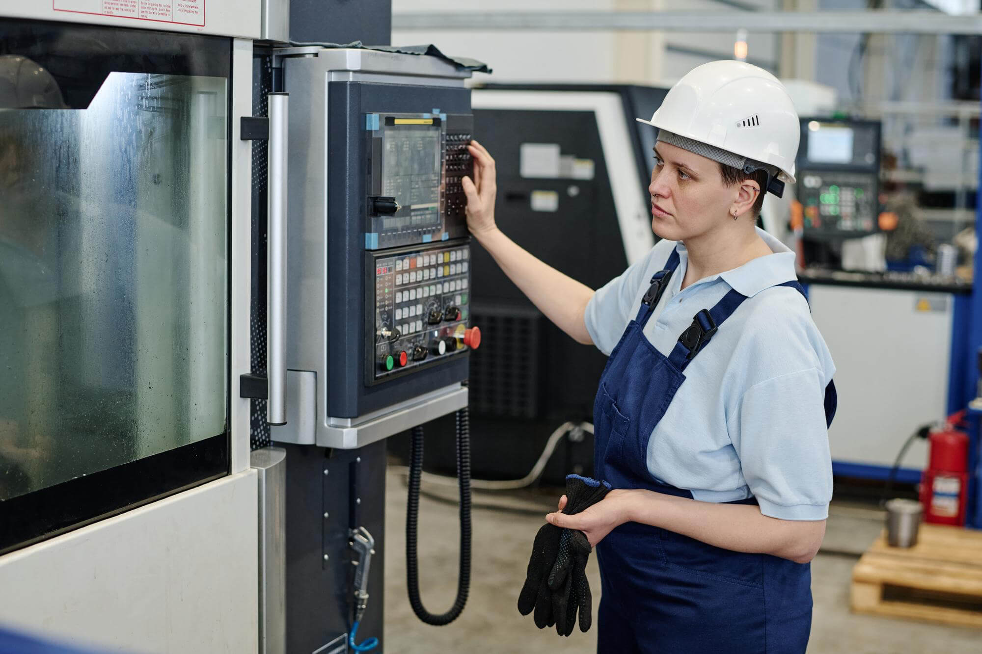
In a CNC machine shop, precision and advanced technology come together in perfect harmony. At the core of this intricate setup is the CNC control system, a crucial element that drives the efficiency and accuracy of machining operations. For those working with CNC machining parts, a deep understanding of the system’s features, parameters, and memory management is vital. Let’s delve into the complexities of these control systems to uncover what makes them indispensable in modern manufacturing.
Control System Features
A CNC control unit is essentially a specialized computer designed to control machine tools like lathes and machining centers. Unlike commercial computers, each CNC unit is built to meet the specific needs of the machine tool manufacturer. This means the control system includes unique features tailored to the machine’s design and performance.
For example, consider two machines with the same functions but different tool-changing mechanisms—one with a manual tool changer and the other with an automatic tool changer. The CNC unit for the machine with the automatic tool changer must include special functions to support this feature. Adding these functions makes the system more complex and expensive, so they’re only included when necessary to avoid unnecessary costs.
Parameter Settings
CNC systems use parameters to establish fixed relationships between the controller and the machine. These parameters are stored in the system’s internal registers. While many parameters are factory-set and require no adjustment, understanding them can help optimize the machining process.
Parameters can be binary codes, input units, or set values. For instance, a binary parameter might switch a feature on or off. Input units could range from millimeters to inches, determining the smallest increment the machine can recognize. Set values might define maximum spindle speeds or feed rates, ensuring the machine operates within safe limits.
Here’s an example of how parameter settings work:
- Binary Parameter: Enables or disables dry run mode (testing movements without cutting).
- Input Unit: Determines if the system measures in millimeters or inches.
- Set Value: Establishes the maximum spindle speed, preventing the machine from exceeding safe limits.
Common Parameter Categories
Fanuc control systems, for example, have parameters categorized into several groups, many of which are relevant only to maintenance technicians:
- Setup Parameters
- I/O Interference Parameters
- Axis Control Data Parameters
- Travel Limit Parameters
- Cutting Parameters
- Pitch Error Compensation Parameters
- Coordinate System Parameters
- Inclination Compensation Parameters
- Feed Rate Parameters
- Straightness Compensation Parameters
- Acceleration/Deceleration Control Parameters
- Spindle Control Parameters
- Servo System Parameters
- Tool Offset Parameters
- DI/DO Parameters
- Fixed Cycle Parameters
- MDI, Edit, and CRT Parameters
- Scaling and Coordinate Rotation Parameters
- Program Parameters
- Automatic Corner Override Parameters
- Spindle Continuous Output Parameters
- Involute Interpolation Parameters
- Graphical Display Parameters
- Unidirectional Positioning Parameters
- Customer Macro (User Macro) Parameters
- Turret Axis Control Parameters
- Program Restart Parameters
- High-Precision Contour Control Parameters
- Rapid Skip Signal Input Parameters
- Maintenance Parameters
- Automatic Tool Compensation Parameters
- Tool Life Management Parameters
Most of these parameters won’t need adjustment by the operator or programmer. However, knowing what they do can help troubleshoot issues or optimize performance.
System Defaults
When manufacturers sell CNC controllers, they often come with pre-set parameters. These default settings are chosen for their broad applicability and safety but might not be the most efficient for all operations. For example, the default rapid movement mode might be set to linear motion (G01 command), which is safer but slower than the rapid traverse (G00 command). Adjusting these defaults can enhance performance but should be done cautiously and usually by experienced personnel.
Memory Management
CNC programs are stored in the controller’s memory. The size of the memory limits the length and complexity of programs that can be stored. Initially, memory capacity was measured in terms of tape length, but now it’s more commonly measured in bytes.
For example, a typical CNC lathe controller might have a minimum memory capacity equivalent to 20 meters (66 feet) of tape, while a CNC milling machine might require 80 meters (263 feet). Choosing a controller with sufficient memory capacity is essential, especially for complex or lengthy programs.
Modern controllers often allow CNC programs to be run directly from a connected PC, a process known as Direct Numerical Control (DNC). This approach bypasses memory limitations by streaming the program from the computer’s storage, which is typically much larger.
Here’s a simple table illustrating the conversion between memory units:
| Measurement Method | Equivalent Memory |
|---|---|
| 20 meters of tape | Approximately 80 KB |
| 80 meters of tape | Approximately 320 KB |
Understanding these conversions helps in planning and selecting the right controller for your needs.
Practical Tips
- Regular Checks: Always verify machine settings before starting a job. This includes tool offsets, work offsets, and ensuring the correct program is loaded.
- Parameter Management: Keep a record of all parameter changes. This log can help troubleshoot issues and revert to previous settings if needed.
- Optimize Defaults: While default settings are safe, optimizing them can enhance performance. However, any changes should be made by qualified personnel.
- Memory Planning: Ensure the controller has enough memory for your most complex programs. Use DNC for larger programs to avoid memory limitations.
- Training: Proper training on using and adjusting the control system can prevent errors and improve efficiency.
Mastering the features, parameters, and memory management of CNC control systems is essential for efficient and precise machining. Each component of the control system, from the control panel to the memory settings, plays a crucial role in the machine’s performance. By understanding and utilizing these features effectively, operators and programmers can enhance their machining processes, leading to better quality parts and increased productivity.
Related Posts
- Precision CNC Machining of Steel: High-Volume Production
Precision CNC Machining and High-Volume Production As an integral part of modern manufacturing processes, Precision Computer Numerical Control (CNC) machining brings about unmatched accuracy and consistency in the production of…
- Material Versatility in CNC Machining: From Titanium to Thermoplastics
Introduction to CNC Machining CNC machining stands as a cornerstone in the manufacturing sector, enabling the precise creation of parts and components. This process utilizes computer numerical control (CNC) to…
- Precision CNC Machining for High-Performance Industrial Machinery
Precision CNC Machining for High-Performance Industrial Machinery The process of Precision CNC (Computer Numerical Control) machining is at the core of manufacturing high-performance industrial machinery. This technique leverages a computer's…
- Nickel vs. Cobalt Alloys in High-Temperature CNC Machining: A Detailed Analysis?
Nickel and Cobalt Alloys in High-Temperature CNC Machining Both Nickel and Cobalt alloys play an essential role in high-temperature CNC machining. These metal alloys are popular choices due to their…
- How to Select the Most Suitable Machining Parameters for Complex Shape Parts in CNC?
Introduction to CNC Machining of Complex Shapes CNC machining has revolutionized the manufacturing industry by enabling the production of complex shapes with high precision and efficiency. This technology utilizes computerized…
- CNC Machining for Medical Applications: Compliance and Material Selection?
Introduction to CNC Machining in Medical Applications CNC or Computer Numerical Control machining is a manufacturing process wherein pre-programmed computer software dictates the movement of factory tools and machinery. This…