Introduction: Why Cam Bearings Matter in CNC Applications
Cam bearings may seem minor, but in precision machining and engine performance, their importance is substantial. Over my years working with engine rebuilds and CNC machining, I’ve seen firsthand how the correct handling of cam bearings directly affects engine performance, durability, and efficiency. Even small inaccuracies in cam bearing installation or machining can lead to severe issues such as accelerated wear, increased friction, overheating, and even catastrophic engine failure.
I remember clearly an incident involving a rebuilt diesel engine in which the cam bearing was slightly misaligned. Within a few hours of operation, excessive vibration and noise were evident. This required immediate disassembly and remachining, costing significant downtime and resources. This event reinforced the necessity of precision CNC machining for cam bearings. Ensuring accurate machining and fitment is not just beneficial—it’s crucial.
What is a Cam Bearing? Basic Function and Variants
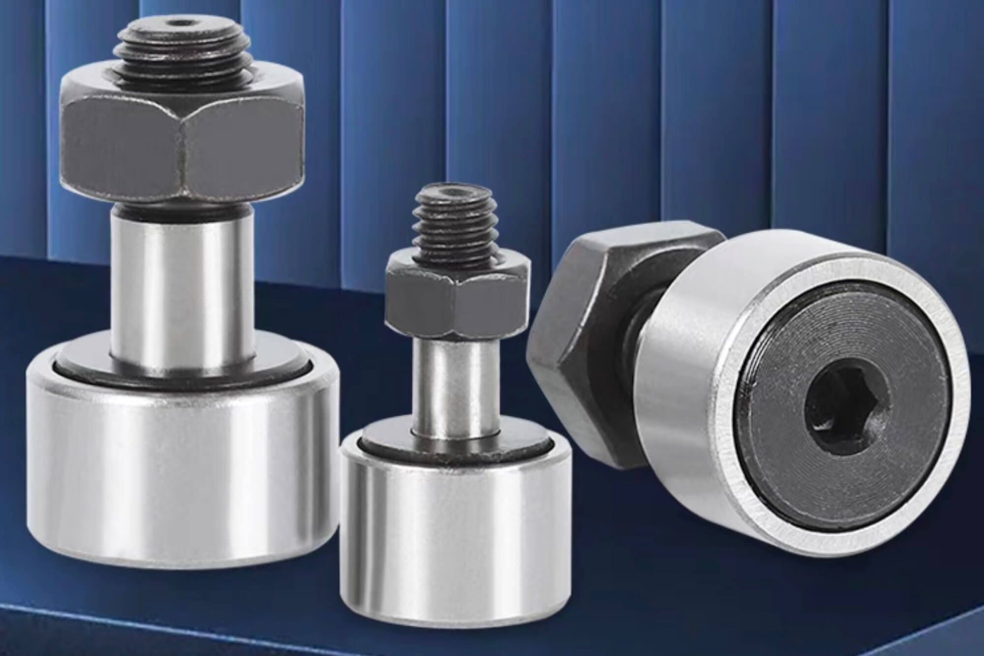
A cam bearing is specifically designed to support the camshaft, allowing it smooth rotation within the engine block or cylinder head. Its primary role is to facilitate precise alignment and maintain proper lubrication to avoid friction and overheating.
Cam Bearing Types and Applications
Cam bearings come in various types, each suited for specific applications:
| Cam Bearing Type | Typical Applications | Advantages | Limitations |
|---|---|---|---|
| Babbitt Bearings | Standard automotive engines | Good lubrication, cost-effective | Limited durability for high loads |
| Tri-metal Bearings | High-performance automotive engines | Exceptional strength and reliability | Higher cost |
| Aluminum Alloy Bearings | General-purpose automotive applications | Economical, good overall performance | Lower durability under high stress |
| Roller Cam Bearings | Racing and high-RPM engines | Superior performance, minimal friction | High cost, complex installation |
| Bronze Bearings | Heavy-duty industrial engines | Excellent durability, heat resistance | Requires careful lubrication |
| Polymer Coated Bearings | Specialized low-friction applications | Low friction, reduced noise | Limited load capacity |
In my experience, selecting the appropriate cam bearing type greatly depends on the application’s demands. For example, tri-metal bearings consistently outperform babbitt bearings in high-performance or racing scenarios.
Where Cam Bearings Are Used: Engines, Equipment, and Automation
Cam bearings have versatile applications beyond automotive use. During my work in industrial equipment maintenance, I frequently encountered cam bearings in diverse settings, such as:
- Automotive engines (cars, trucks, motorcycles)
- Marine engines (inboard and outboard motors)
- Agricultural machinery (tractors, harvesters)
- Heavy industrial equipment (compressors, pumps)
- Performance and racing engines
- Generators and stationary power units
One particularly memorable project involved machining cam bearing housings for large marine diesel engines. The project highlighted the importance of robust CNC processes due to the extreme operational loads these bearings experience in marine environments.
Precision Fitment: Why CNC Machining Is Critical for Cam Bearing Installations
Precision in cam bearing installation cannot be overstated. CNC machining offers unmatched accuracy, repeatability, and surface finish quality necessary for reliable cam bearing performance. Through my direct experience, CNC machining has repeatedly demonstrated advantages over manual machining techniques:
- Consistency and Repeatability: CNC ensures identical results across batches, essential for quality control.
- Tight Tolerance Achievement: Capable of consistently maintaining tolerances as fine as ±0.005 mm.
- Superior Surface Finishes: Smooth, precise finishes that optimize lubrication retention and reduce friction.
I recall a client who initially tried manual boring methods and faced persistent issues with bearing alignment and premature failures. After transitioning to CNC machining, the client achieved consistent reliability and substantially reduced rework.
CNC Machining Processes for Cam Bearing Bores and Seats
Cam bearing machining primarily involves CNC milling and line-boring, each method offering distinct advantages:
CNC Milling
- Setup: Precise alignment and clamping of engine blocks.
- Procedure: Use of precision boring heads or specialized end mills to machine bearing seats.
- Advantages: Highly adaptable, suitable for customized or small-batch machining.
CNC Line-Boring
- Setup: Engine blocks aligned in specialized line-boring fixtures.
- Procedure: Simultaneous boring of multiple bearing bores, ensuring perfect alignment.
- Advantages: Superior for multi-bearing applications, ensuring uniform alignment.
| CNC Method | Precision Alignment | Ideal Usage | Cost/Complexity |
|---|---|---|---|
| CNC Milling | High (single bore) | Customized machining, prototypes | Moderate |
| CNC Line-Boring | Very High | Multiple aligned bores | Higher investment |
In practice, line-boring is my preferred method for automotive engine rebuilds due to its exceptional accuracy and alignment.
Material Selection and Surface Finish for Cam Bearing Applications
Correct material choice and surface finish are pivotal for cam bearing longevity and performance. Different engine block materials significantly impact machining processes and results. Here’s an expanded overview based on my practical experience:
| Engine Material | Optimal Cutting Speed | Optimal Feed Rate | Recommended Surface Finish (Ra) |
|---|---|---|---|
| Cast Iron | 90–130 m/min | 0.05–0.15 mm/rev | 0.8–1.2 µm |
| Aluminum Alloy | 180–260 m/min | 0.05–0.2 mm/rev | 0.4–0.8 µm |
| Hardened Steel | 60–90 m/min | 0.04–0.10 mm/rev | 0.6–1.0 µm |
| Bronze Alloys | 100–150 m/min | 0.05–0.12 mm/rev | 0.8–1.2 µm |
| Polymer Composites | 150–200 m/min | 0.03–0.08 mm/rev | 0.4–0.6 µm |
| Stainless Steel | 50–80 m/min | 0.03–0.10 mm/rev | 0.6–1.0 µm |
Surface finish greatly impacts bearing performance; too rough increases friction, whereas too smooth can impede proper lubrication adherence. Typically, an Ra of around 0.8 µm strikes an optimal balance for most automotive applications. Ensuring accurate feed rates and cutting speeds is critical; deviation can significantly degrade the surface quality.
Through meticulous attention to material-specific machining parameters, I’ve consistently achieved improved bearing lifespan and reduced operational issues.
Common Issues in Cam Bearing Installations and CNC Fixes
Cam bearing installation and machining don’t always go smoothly. Through years of engine rebuilds and precision machining, I’ve faced various challenges repeatedly. Here are some of the most common issues and how CNC machining solves them effectively.
Issue #1: Misalignment of Cam Bearings
Misalignment causes uneven wear, vibration, and potentially catastrophic failure. It’s usually due to inconsistent manual machining or improper fixturing.
CNC Solution:
By using CNC line-boring, alignment precision improves dramatically. Automated alignment tools ensure bores remain consistent and perfectly centered.
Issue #2: Incorrect Bore Sizing
Incorrect bore size, either too large or small, causes either loose bearings that spin or overly tight bearings causing friction.
CNC Solution:
CNC machines excel in maintaining strict tolerances within ±0.005 mm, ensuring bore sizes consistently match specifications.
Issue #3: Poor Surface Finish
Rough surfaces accelerate bearing wear, while overly smooth surfaces can compromise lubrication adherence.
CNC Solution:
Modern CNC machines easily produce the precise surface finish required (0.6–1.2 µm Ra). Adjusting spindle speed and feed rate ensures consistently ideal finishes.
Issue #4: Spun Cam Bearings
Bearings spinning in their housings typically result from inadequate interference fit or poor surface quality.
CNC Solution:
Precision machining of interference fit clearances (typically 0.01–0.05 mm interference) prevents bearings from spinning. CNC control ensures reliable, repeatable dimensions.
Issue #5: Out-of-Round Bores
Manual machining can lead to oval-shaped or distorted bores, causing premature bearing failure.
CNC Solution:
CNC ensures geometric precision, machining perfectly circular bores that enhance bearing longevity.
Issue #6: Lubrication Issues
Improper bore geometry or inadequate oil grooves cause lubrication problems.
CNC Solution:
CNC machines can precisely mill oil grooves or chamfers, improving lubrication pathways and bearing performance.
Case Study: Re-machining a Cam Bearing Housing in an Automotive Engine
I once worked on rebuilding an automotive V8 engine with severely worn cam bearing housings. The customer had tried manual honing, leading to oversized and misaligned bearing seats. CNC machining offered a comprehensive fix.
Step-by-Step CNC Repair Process
Step 1: Inspection and Measurement
- Initial measurements showed bores oversized by 0.3–0.5 mm and misaligned by 0.1 mm.
- Used precision bore gauges and alignment tools to assess the damage.
Step 2: CNC Setup and Fixturing
- Engine block secured in a CNC machining center using dedicated alignment fixtures.
- Verified alignment accuracy within ±0.01 mm.
Step 3: Precision CNC Line-Boring
- Programmed CNC machine to remove minimal material, maintaining structural integrity.
- Held bore diameter tolerance within ±0.005 mm for a precise interference fit.
Step 4: Surface Finish and Oil Grooves
- Achieved optimal surface finish of 0.8 µm Ra.
- CNC-machined oil grooves to OEM specifications.
Step 5: Installation of Cam Bearings
- Pressed bearings with precision alignment tools, verifying interference fit.
- Final inspection confirmed bore alignment within specifications.
Results and Lessons Learned
Post-machining, the rebuilt engine ran smoothly with no cam bearing issues, demonstrating the CNC’s capability to fix severe bore damage accurately and effectively. This experience reinforced my confidence in CNC machining as essential for engine rebuild precision.
Selecting the Right Cam Bearing: Load, Speed, and CNC Considerations
Choosing the right cam bearing requires understanding the application-specific requirements. Here’s my approach:
Load Considerations
- High-load applications (performance engines): Tri-metal or roller bearings.
- Moderate loads (standard automotive): Aluminum or babbitt bearings.
Speed and Performance
- High RPM scenarios: Roller or polymer-coated bearings offer low friction.
- Standard operating conditions: Aluminum alloy bearings provide balanced performance.
CNC Machining Compatibility
- Ensure the chosen bearing type matches your CNC machining capabilities (surface finishes, bore tolerances, oil groove complexity).
Selection Guide Table:
| Application | Recommended Bearing | Load Capacity | CNC Compatibility |
|---|---|---|---|
| Standard Automotive | Aluminum or Babbitt | Moderate | Excellent |
| Performance Automotive | Tri-metal | High | Excellent |
| Racing Applications | Roller bearings | Very High | Moderate |
| Industrial Machinery | Bronze bearings | High | Excellent |
| Marine Engines | Tri-metal or Bronze | High | Excellent |
| Agricultural Equipment | Aluminum or Babbitt | Moderate | Excellent |
From experience, ensuring CNC capabilities align with bearing choice consistently reduces installation complications and improves long-term reliability.
CNC Tooling, Fixturing, and Setup Tips for Cam Bearing Jobs
Proper tooling and setup greatly influence machining outcomes. Here are proven recommendations:
CNC Tooling
- High-quality carbide boring bars and inserts.
- Precision-ground boring heads for accuracy.
Fixturing
- Dedicated engine block fixtures ensuring perfect alignment.
- Adjustable alignment jigs for various engine models.
Setup Tips
- Always verify alignment using precision dial indicators before machining.
- Use consistent coolant flow to maintain surface finish.
- Double-check program parameters for speed, feed, and depth before running production.
Tooling and Fixturing Recommendations:
| Component | Recommended Specifications | Why It Matters |
|---|---|---|
| Boring Bars | Carbide, high rigidity | Minimizes chatter, enhances finish |
| Inserts | Coated carbide, specific to material type | Optimizes cutting performance |
| Alignment Fixtures | Precision-machined steel, adjustable | Ensures accurate repeatability |
| Dial Indicators | 0.001 mm accuracy | Critical for verifying alignment |
| Coolant | High-quality synthetic machining coolant | Maintains surface quality |
| Tool Holders | Hydraulic or shrink-fit holders | Ensures tool rigidity |
Through rigorous adherence to these practices, I’ve achieved consistently successful cam bearing machining outcomes.
Conclusion
Over years of hands-on machining and engine rebuilding, I’ve consistently seen CNC machining prove its worth in cam bearing applications. Whether dealing with standard automotive engines or high-performance racing scenarios, CNC ensures precision, repeatability, and reliability.
The key takeaways for reliably machining and installing cam bearings with CNC are:
- Prioritize precision alignment and bore sizing.
- Choose bearings based on application demands.
- Implement robust tooling and fixturing practices.
- Regularly verify tolerances and surface finishes.
By following these principles, you significantly reduce the risk of bearing failure, improve equipment reliability, and streamline your machining processes.
Ultimately, CNC machining is indispensable for anyone serious about quality, precision, and long-term reliability in cam bearing applications. My own journey has shown that attention to detail and a commitment to precision machining practices consistently pay off in enhanced performance and client satisfaction.
FAQ
1. What is a cam bearing, and why is it important?
A cam bearing supports the camshaft within an engine, allowing it to rotate smoothly. Proper installation ensures optimal engine performance and longevity.
2. Can CNC machines be used to install cam bearings?
Yes, CNC machines provide the precision required for accurate cam bearing installation, ensuring proper alignment and fit.
3. How precise does the bore need to be for a cam bearing?
Bore precision is critical; tolerances often need to be within ±0.005 mm to ensure proper fit and function.
4. What materials are commonly used in cam bearings?
Common materials include babbitt, aluminum alloys, and tri-metal composites, each offering different performance characteristics.
5. How do I know if my engine’s cam bearing bore is out of spec?
Signs include unusual engine noises, decreased performance, or visible wear. Precision measuring tools can confirm bore dimensions.
6. What types of CNC machines are best for machining cam bearing seats?
CNC milling machines and line-boring machines are commonly used for this purpose due to their precision and control.
7. Can I re-machine a worn cam bearing bore using CNC?
Yes, CNC machining can restore worn bores to their original specifications, ensuring proper bearing fit.
8. What’s the best way to achieve an interference fit with a cam bearing?
Careful CNC machining to precise dimensions ensures the correct interference fit, typically a slight oversize of the bearing relative to the bore.
9. Are there pre-sized cam bearings for CNC-based rebuilds?
Yes, many manufacturers offer cam bearings in standard sizes suitable for CNC-machined bores.
10. How do I prevent misalignment during cam bearing installation?
Using proper CNC machining techniques and alignment tools ensures accurate placement and alignment of cam bearings.
11. What surface finish is required for a cam bearing housing?
A smooth surface finish, typically around 0.8 µm Ra, is recommended to ensure proper bearing function and longevity.
12. Can I use CNC turning or milling for cam bearing-related work?
Yes, both CNC turning and milling can be employed, depending on the specific requirements of the cam bearing installation.
13. What tolerances should I hold when cutting cam bearing bores?
Tolerances should generally be within ±0.005 mm to ensure proper bearing fit and function.
14. Is it possible to upgrade cam bearings using custom CNC machining?
Yes, CNC machining allows for customization and upgrading of cam bearing installations to meet specific performance needs.
15. How do I press-fit cam bearings accurately after CNC machining?
Using specialized tools and ensuring the bore is machined to the correct dimensions facilitates accurate press-fitting of cam bearings.
16. What should I do if a cam bearing spins in its housing?
This indicates an improper fit; re-machining the bore and replacing the bearing is typically necessary.
17. Can CNC be used for batch production of cam bearing carriers or caps?
Absolutely, CNC machining is ideal for producing consistent, high-quality components in batch quantities.
Authoritative References for Further Reading
To deepen your understanding of cam bearings and CNC machining, consider exploring the following reputable sources:
- Wikipedia – Camshaft
An overview of camshaft functions and applications.
https://en.wikipedia.org/wiki/Camshaft - Wikipedia – CNC Machine Tools
Detailed information on CNC machines and their operations.
https://en.wikipedia.org/wiki/CNC_machine_tool - Engine Pro – Camshaft Bearing Fundamentals
Insights into camshaft bearing installation and considerations.
https://enginepro.com/camshaft-bearing-fundamentals/ - Hot Rod Magazine – Cam Bearing Installation Guide
Practical advice on installing cam bearings in performance engines.
https://www.hotrod.com/how-to/0411rc-cam-bearing-installation/ - Fictiv – The Ultimate Guide to CNC Machining
Comprehensive guide covering CNC machining processes and best practices.
https://www.fictiv.com/articles/the-ultimate-guide-to-cnc-machining - Autodesk Fusion Blog – CNC Machining 101
An introduction to CNC machining, including design and manufacturing considerations.
https://www.autodesk.com/products/fusion-360/blog/cnc-machining-101-a-comprehensive-guide/ - AT-Machining – CNC Machining Precision
Explores the precision aspects of CNC machining and its applications.
https://at-machining.com/cnc-machining-precision/ - Wikipedia – NCSIMUL
Information on CNC simulation software used for verifying and optimizing machining processes.
https://en.wikipedia.org/wiki/NCSIMUL
Other Articles You Might Enjoy
- Custom Ball Bearing Manufacturing with CNC: Who Needs It and What’s Possible
Introduction: Why Custom Ball Bearings Are Gaining Popularity I’ve been fascinated by mechanical components ever since I first saw the inside of a small gearbox in college. Back then, I…
- Pinion Bearing Custom Manufacturing: From Concept to Finished Part
I. Introduction: What Is a Pinion Bearing and Why CNC Matters When I first started designing mechanical assemblies, I often heard people talk about a “pinion bearing.” It seemed like…
- Complete Guide to Crankshaft Bearing Machining: Applications, Equipment, and Optimization
I. Introduction Crankshaft bearing is among the most critical component within engines and mechanical systems. They directly affect performance, durability, and efficiency by supporting the rotation of the crankshaft and…
- Complete Guide to Sleeve Bearing Machining: Techniques, Applications, and CNC Optimization
I. Introduction If you've worked around machinery or mechanical components, you've probably encountered a sleeve bearing at some point. Sleeve bearings, also known as plain bearings or bushings, are simple components designed…
- How to Achieve High-Precision Bearing Race Production with CNC Machining
I. INTRODUCTION I remember the first time I got involved with bearing race production. Back then, I struggled to understand why these simple-looking rings needed such tight tolerances. Yet the…
- Understanding Wheel Hub Bearing And How CNC Machining Ensures Precision
Chapter 1: Why Understanding Wheel Hub Bearings and CNC Machining Matters A wheel hub bearing is a critical component in virtually every vehicle on the road.When I first learned about…
- Main Bearing Performance Boost: How to Achieve It with CNC Machining
Chapter 1:Introduction I remember the first time I heard someone ask, “Isn’t a main bearing just a regular bearing?”My immediate thought was that a main bearing is more specialized than…
- Flange Bearing Manufacturing & Buying Guide: CNC Machining vs. Ready-to-Use Bearings
Introduction: What Are Flange Bearings and Why Are They Important? I can still remember the first time I came across the term “flange bearing.”It was early in my career, back when…
- About Pilot Bearing: Design Customizing Tips, CNC Machining Insights, and Sourcing Guide
Introduction A pilot bearing may seem like a small component, but it plays a critical role in the smooth operation of clutch systems, transmission assemblies, and industrial equipment. Its purpose…
- Linear Bearing Guide: Types, Applications, and Selection Tips for CNC Systems
Introduction If you’ve worked with CNC machines, you know how critical precision and smooth motion are to achieving consistent results. At the heart of this precision lies an often-overlooked component:…


