Introduction to CAD and CNC Machining
The world of manufacturing has been drastically transformed by two innovative technologies: Computer-Aided Design (CAD) and Computer Numerical Control (CNC) machining. CAD, a technology that aids in the conceptualization, design, and drafting of products using computer systems, plays an integral role in modern production processes. It’s counterpart, CNC machining, is a manufacturing method where pre-programmed software dictates the movement of factory tools and machinery. From creating simple objects to complex parts for machines and structures, these advancements have provided a significant boost to precision, efficiency, and flexibility in the field. However, there’s often a steep learning curve associated with understanding how to effectively transition from CAD designs to tangible CNC-produced prototypes or products without a technical background.
Understanding Computer-Aided Design (CAD)
Computer-Aided Design, often referred to as CAD, is a simplified software system that aids in the creation, modification, and analysis of design. It’s an essential tool for architects, engineers, and industrial designers due to its ability to streamline product design and layout processes. In basic terms, CAD works by allowing professionals to draft up two-dimensional or three-dimensional models on their computer screens rather than having to hand-draw them out on paper. This not only speeds up the designing process but also enhances precision and efficacy. A real-world application of CAD can be seen in automotive manufacturing where it’s used extensively for car design — from the initial concept phase right down to the production of parts.
Comprehending CNC (Computer Numerical Control)
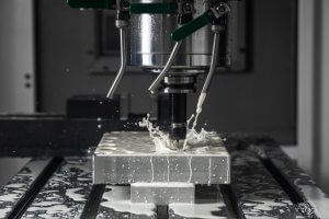
A Computer Numerical Control, or CNC machine is a high-precision tool that’s computer-controlled and makes repeated, exact movements. Its purpose is to speed up the manufacturing process while improving product consistency. The benefits of using a CNC machine in manufacturing include its efficiency and precision in making complex cuts which would otherwise be nearly impossible manually.
The operation process of a CNC begins when engineers design a product with CAD software then upload this design to the CNC machine’s program, essentially giving it specific instructions on what actions to take. Once set up, the machine automatically follows these commands by cutting raw material into designed shapes with extreme accuracy, all without direct human control.
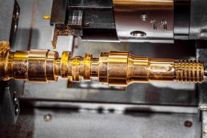
For example, CNC machines have revolutionized the automobile industry. They are used to manufacture car parts with high precision such as engine components, gears etc., thus allowing mass production of cars possible with uniform standards. Similarly, in the aerospace industry, CNC machines enable the fabrication of intricate shapes on materials like titanium which can withstand harsh space conditions, contributing heavily to maintaining high safety standards in spacecraft construction.
markdown
### Detailed Workflow from CAD to CNC Machine Operations
The transition from CAD designs to CNC machine operations is a critical pathway in the manufacturing process, ensuring that the digital blueprints become tangible products with precision. This detailed workflow encapsulates the meticulous steps involved in turning a CAD model into a finished part through CNC machining.
#### Step 1: Design Creation Using CAD Software
The process initiates with the creation of a detailed design using CAD software. This digital model precisely outlines the dimensions, features, and tolerances of the desired part, serving as the foundational blueprint for the manufacturing process.
#### Step 2: Preparing CAD Files for CNC Machining
Once the design is finalized, the CAD files must be prepared for CNC machining. This involves converting the files into a format recognizable by CNC machines, typically the STEP format. This conversion ensures that the design is accurately interpreted by the CNC equipment.
#### Step 3: Translating CAD Designs into CNC Programs
The prepared CAD files are then translated into CNC programs using CAM (Computer-Aided Manufacturing) software. This critical step involves generating machine-readable instructions that guide the CNC machine’s movements and actions based on the CAD model.
#### Step 4: CNC Machine Setup
Before the machining begins, the CNC machine requires setup. This includes:
– Loading the CNC program into the machine.
– Setting up the tooling, including the selection and installation of the appropriate cutting tools.
– Securing the workpiece onto the machine, ensuring it is properly aligned and fixed in place.
#### Step 5: Running the CNC Program
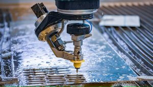
With the machine set up and the program loaded, the CNC machining process commences. The machine follows the programmed instructions, performing actions such as cutting, milling, turning, and electrical discharge machining to sculpt the part from the workpiece.
#### Step 6: Quality Assurance and Inspection
After the machining process, the part undergoes a thorough inspection to ensure it meets the specified dimensions, features, and tolerances outlined in the CAD model. This quality assurance step is crucial for verifying the accuracy and quality of the manufactured part.
#### Table: Workflow from CAD to CNC Machine Operations
| Step | Description |
|——|————-|
| 1. Design Creation Using CAD Software | Creation of a detailed digital model outlining the part’s specifications. |
| 2. Preparing CAD Files for CNC Machining | Conversion of CAD files into a CNC-compatible format. |
| 3. Translating CAD Designs into CNC Programs | Generation of machine-readable instructions using CAM software. |
| 4. CNC Machine Setup | Preparation of the CNC machine, including tooling and workpiece setup. |
| 5. Running the CNC Program | Execution of the CNC program to machine the part. |
| 6. Quality Assurance and Inspection | Inspection of the finished part to ensure it meets all specifications. |
This workflow highlights the seamless integration of CAD and CNC technologies, enabling the precise and efficient production of parts. By meticulously following these steps, manufacturers can ensure that the transition from digital designs to physical products is executed with the highest standards of accuracy and quality.
Common Misunderstandings and Challenges in CAD to CNC Workflow
The transition from Computer-Aided Design (CAD) to Computer Numerical Control (CNC) machining can be fraught with misunderstandings and challenges. One common misconception is that the programming for this process is overly complicated to comprehend and execute. While CAD to CNC programming indeed carries a degree of complexity, years of technology advancements have simplified it considerably. For instance, modern software tools often come equipped with user-friendly interfaces and tutorials, offering efficient coding and better comprehensibility.
Another potential difficulty encountered during this workflow revolves around material inconsistencies leading to suboptimal outcomes. The accurate conversion from CAD model to a final physical product demands tight control over numerous variables like tool type, cutting speed, spindle speed, etc., any deviations from which may lead to inefficient results. However, careful planning, along with regular calibration and condition monitoring of machines, typically mitigates these concerns.
A case illustrating challenges involved includes firms unexpectedly facing dimensional inaccuracies due to fluctuations in environmental conditions affecting material properties. Many organizations learning this hard way are now taking extra precautions such as acclimatizing materials before processing them, thus significantly reducing causes of their earlier woes.
Potential Outcomes of Effective CAD to CNC Workflow
When properly implemented, the transition from Computer-Aided Design (CAD) to Computer Numerical Control (CNC) machining can lead to numerous benefits. Prime among them is increased manufacturing efficiency. For instance, a company that optimizes its CAD to CNC workflow may streamline its production processes, thereby reducing the time it takes for a product to move from concept to reality. In another example, finely-tuned workflows can reduce errors commonly encountered when translating a digital design into a physical one which reduces waste and subsequently cuts down on material costs.
A successful transition could also significantly impact overall production costs and timelines. The decrease in timeline due to reduced manual work translates into quicker completion times and lower labor costs. With fewer errors comes less time and resources spent on correcting these mistakes, leading to substantial savings over time as well. Moreover, by understanding this workflow more thoroughly, companies may further enhance their operational efficiencies – contributing to larger profit margins in the long run. According to research data, companies that have effectively transitioned their CAD to CNC workflows have reported an up to 50% reduction in production time and nearly 30% cost savings in certain cases. This underlines the importance of understanding and implementing this workflow meticulously in any production-based business setting.
Related Posts
- Preparing Your CAD Model for CNC Machining
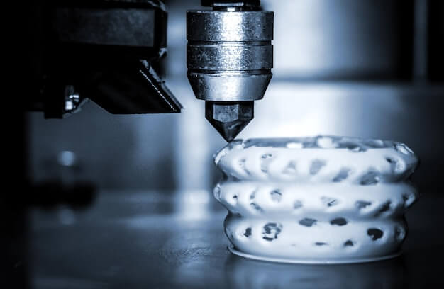
CNC machining has emerged as a go-to solution for manufacturing prototypes and parts involving cutting or drilling. This technology harnesses the power of a rotating cylindrical cutting tool to shape…
- Precision CNC Machining of Steel: High-Volume Production
Precision CNC Machining and High-Volume Production As an integral part of modern manufacturing processes, Precision Computer Numerical Control (CNC) machining brings about unmatched accuracy and consistency in the production of…
- How to Optimize Your CAD Models for CNC Machining
In this article, we will explore the essential steps to optimize your CAD models for CNC machining. We will delve into various aspects such as geometry, tolerances, material selection, and…