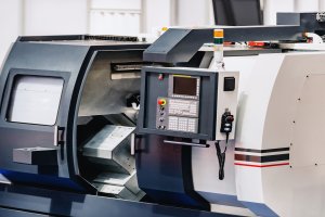
Walking into a CNC machine shop can feel like stepping into a high-tech wonderland. Rows of sophisticated machines, each equipped with numerous buttons, screens, and switches, might seem intimidating at first. But understanding these control systems is crucial for anyone involved in CNC machining. Let’s break down the control systems of CNC machines, from the control panels to the handwheels, in a straightforward and engaging way.
The Importance of Control Systems
The control system of a CNC machine is its brain. It’s what allows precise and automated control over the machining process. The control unit typically consists of two main parts: the operator panel and the display with a keyboard. While programmers usually don’t interact with these controls during their day-to-day tasks, operators rely heavily on them to set up, debug, and run machining processes.
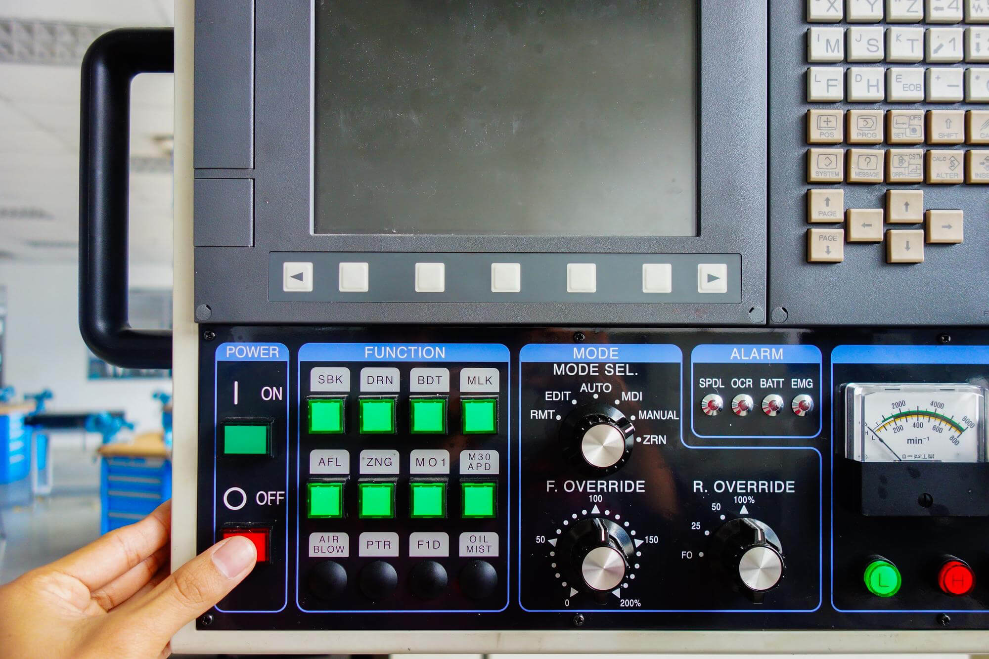
Key Components of the Control Panel
The control panel is the interface between the operator and the machine. It includes various switches, buttons, and knobs that allow the operator to control the machine’s movements and functions. Here are some of the most common features you’ll find on a modern CNC machine’s control panel:
| Feature | Description |
|---|---|
| ON/OFF Switch | Main power switch for the machine and control system |
| Cycle Start | Begins the execution of a program or MDI command |
| Emergency Stop | Immediately halts all machine operations and powers down the control unit |
| Feed Hold | Pauses the movement of all axes |
| Single Block | Executes the program one block at a time |
| Optional Stop | Pauses the program execution at M01 commands |
| Block Skip | Ignores program blocks marked with a slash (/) |
| Dry Run | Runs the program without cutting to verify movements |
| Spindle Override | Adjusts the programmed spindle speed, usually between 50% and 120% |
| Feedrate Override | Adjusts the programmed feed rate, usually between 0% and 200% |
| Chuck Clamp | Displays the current chuck clamping state |
| Table Clamp | Displays the current worktable clamping state |
| Coolant Switch | Controls the coolant flow (ON/OFF/AUTO) |
| Gear Selection | Shows the current gear ratio selection |
| Spindle Rotation | Indicates the direction of spindle rotation (clockwise or counterclockwise) |
| Spindle Orientation | Manually positions the spindle |
| Tool Change | Allows manual tool changes |
| Reference Position | Moves the machine to its reference position |
| Handwheel (MPG) | Manual pulse generator for precise control over axis movements |
| Tailstock Switch | Manually positions the tailstock |
| Indexing Table Switch | Manually indexes the worktable during setup |
| MDI Mode | Manual Data Input mode for direct command entry |
| AUTO Mode | Enables automatic operation |
| MEMORY Mode | Runs programs from the CNC’s internal memory |
| TAPE/EXT or DNC Mode | Executes programs from an external device |
| EDIT Mode | Allows editing of programs stored in memory |
| MANUAL Mode | Enables manual machine operation during setup |
| JOG Mode | Enables jogging of the machine axes during setup |
| RAPID Mode | Enables rapid movement of the machine axes during setup |
| Memory Access | Keypad for program editing and control |
| Error Lights | Red lights indicating errors |
The Display and Keyboard
The display screen is the window into the machine’s operations. It shows the current program, machine status, tool positions, offsets, parameters, and even graphical tool paths. Operators can use the keyboard and soft keys to enter commands, modify programs, or adjust machine settings. Displays are often customizable, allowing operators to choose between different views and languages to best suit their needs.
Handwheels for Precision Control
Handwheels, or Manual Pulse Generators (MPGs), provide fine control over the machine’s movements. They are especially useful during setup and debugging, allowing operators to move the selected axis in very small increments. The handwheel typically has settings for different incremental steps (e.g., X1, X10, X100), enabling precise positioning.
| Handwheel Settings | Metric System | Imperial System |
|---|---|---|
| X1 | 0.001 mm per step | 0.0001 in per step |
| X10 | 0.010 mm per step | 0.0010 in per step |
| X100 | 0.100 mm per step | 0.0100 in per step |
Practical Tips for Using CNC Control Systems
- Regular Checks: Always check the machine’s settings before starting a job. Verify the tool offsets, work offsets, and ensure the correct program is loaded.
- Emergency Protocols: Familiarize yourself with the emergency stop procedures and ensure that all operators know how to quickly halt the machine if needed.
- Feed and Speed Adjustments: Use spindle and feed rate overrides judiciously to fine-tune the machining process. This can help avoid tool wear and improve the quality of the finished part.
- Program Verification: Utilize dry runs and single block execution to verify the program before cutting. This helps catch potentia
- Maintenance: Regularly clean and maintain the control panel, display, and handwheel to ensure they function correctly and prevent dust or debris from causing issues.
Mastering the control systems of CNC machines is essential for efficient and accurate machining. From the numerous buttons and switches on the control panel to the detailed readouts on the display screen and the precision adjustments of the handwheel, each component plays a critical role. By understanding and effectively using these systems, operators can ensure smooth operations, high-quality outputs, and a safer working environment.
Other Articles You Might Enjoy
- Applications and Advantages of Bronze CNC Machining
1. Introduction: The Enduring Allure of Bronze in CNC Machining In this opening section, we explore the timeless appeal of bronze as a material for CNC machining. From its rich…
- Innovative CNC Machining for Complex Surgical Tools
Introduction to CNC Machining and its Significance in Surgical Tools Manufacturing CNC machining, an acronym for Computer Numerical Control machining, plays a significant role in the manufacturing world. Being an…
- Precision CNC Machining of Steel: High-Volume Production
Precision CNC Machining and High-Volume Production As an integral part of modern manufacturing processes, Precision Computer Numerical Control (CNC) machining brings about unmatched accuracy and consistency in the production of…
- Material Versatility in CNC Machining: From Titanium to Thermoplastics
Introduction to CNC Machining CNC machining stands as a cornerstone in the manufacturing sector, enabling the precise creation of parts and components. This process utilizes computer numerical control (CNC) to…
- Tapping Methods in CNC Machining
Classification and Characteristics of Tapping in CNC Machining Tapping, using taps to machine threaded holes, is the most commonly used method for creating threaded holes. It is mainly suitable for…
- Precision CNC Machining for High-Performance Industrial Machinery
Precision CNC Machining for High-Performance Industrial Machinery The process of Precision CNC (Computer Numerical Control) machining is at the core of manufacturing high-performance industrial machinery. This technique leverages a computer's…