Introduction
In the pursuit of precision, rigidity, and compact designs, crossed roller bearings are pivotal in advancing engineering fields like robotics, medical imaging, and machine tools. These crossed roller bearings are not mere components; they enable innovation by managing multi-axis loads with exceptional rigidity in a minimal footprint. A single crossed roller bearing often replaces dual-bearing setups, such as angular contact ball bearings, reducing space, weight, and assembly complexity. This expert-level guide empowers engineers with a deep understanding of crossed roller bearings, covering mechanics, anatomy, performance, and application-specific selection to optimize system performance. Explore our bearing selection guide (#) to leverage crossed roller bearings today.
1.Foundational Principles and Operating Mechanics of Crossed Roller Bearings
The remarkable capabilities of a crossed roller bearing stem from its ingenious design. Understanding its mechanics—from structure to performance—is critical for effective implementation.
1.1 Orthogonal Roller Arrangement: Revolutionizing Load Management
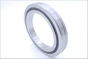
The defining feature of a crossed roller bearing is its orthogonal roller geometry. Cylindrical rollers are arranged alternately at 90-degree angles within a V-shaped raceway, each roller perpendicular to its neighbor. This design enables the crossed roller bearing to handle radial, axial, and moment loads simultaneously, making it ideal for robotics and machine tools. Unlike conventional bearings, a single crossed roller bearing eliminates the need for multiple units, simplifying designs. The unique structure of crossed roller bearings ensures exceptional performance in high-precision systems.
1.2 Line Contact vs. Point Contact: Superior Rigidity and Load Capacity
The crossed roller bearing operates on line contact, where cylindrical rollers engage the raceway along their length, unlike ball bearings’ point contact. This fundamental difference drives the crossed roller bearing’s advantages. Line contact distributes forces over a larger area, reducing contact stress and enabling crossed roller bearings to support heavier loads. It also minimizes elastic deformation, yielding rigidity three to four times greater than ball bearings. This high stiffness ensures the crossed roller bearing delivers rotational accuracy, minimizing deflection and vibration in demanding applications like medical scanners.
2. Anatomy of a Crossed Roller Bearing
To select and apply a crossed roller bearing, engineers must understand its components and design variations, which tailor performance to specific needs.
2.1 Inner and Outer Rings: The Backbone of Crossed Roller Bearings
The inner and outer rings form the structural core of a crossed roller bearing, typically made from high-quality bearing steel. Key configurations include:
- Split Outer Ring (e.g., CRBA, RA Series): In this crossed roller bearing, a solid inner ring rotates while a two-piece outer ring, secured by bolts, remains stationary. It simplifies preload adjustment.
- Split Inner Ring (e.g., CRBB, RE Series): This crossed roller bearing features a solid outer ring and a split inner ring, ideal for outer ring rotation.
- Integral Rings (e.g., CRBC, RU Series): Both rings are solid, offering maximum rigidity and accuracy in crossed roller bearings for high-precision applications like optical instruments.
The ring configuration in a crossed roller bearing impacts mounting and stability.
2.2 Rolling Elements: Cylindrical vs. Tapered Rollers
Most crossed roller bearings use cylindrical rollers, but crossed tapered roller bearings employ conical rollers for enhanced rigidity and moment load capacity. These are specified for demanding applications, such as vertical boring machines, where crossed roller bearings ensure unparalleled stiffness.
2.3 Guidance Systems: Cages, Separators, and Full Complement
Guidance systems maintain roller alignment in crossed roller bearings:
- Cage: A resin or metal structure holds rollers, reducing friction for high-speed crossed roller bearings.
- Separator: Spacers prevent roller contact, balancing load and speed.
- Full Complement: Maximizes rollers for the highest load capacity in low-speed crossed roller bearings, but increases friction.
2.4 Sealing and Integrated Mounting
Crossed roller bearings come in open or sealed configurations. Sealed crossed roller bearings use rubber seals to protect against contaminants, ensuring longevity in industrial environments. Models with integrated mounting holes (e.g., CRBE, RU Series) allow direct bolting to machine frames, reducing parts, assembly time, and weight in compact crossed roller bearing applications like robotics.
3. Comparative Analysis of Crossed Roller Bearings
Selecting a crossed roller bearing requires understanding its trade-offs against alternatives like angular contact ball bearings and tapered roller bearings.
3.1 Crossed Roller Bearings vs. Angular Contact Ball Bearings
- Load & Rigidity: The crossed roller bearing’s line contact provides higher load capacity and three to four times greater rigidity than ball bearings.
- Speed & Friction: Ball bearings offer lower friction and higher speeds, while crossed roller bearings have tighter rotation due to preload.
- Footprint: A single crossed roller bearing replaces paired ball bearings, saving space and simplifying housing design.
- Cost: While a crossed roller bearing costs more per unit, system-level savings from reduced components make it competitive.
3.2 Crossed Roller Bearings vs. Tapered Roller Bearings
- Load Handling: A crossed roller bearing supports bi-directional axial loads, unlike single tapered roller bearings requiring paired setups.
- Precision: Crossed roller bearings excel in high-precision applications like robotics, while tapered roller bearings suit heavy-duty machinery.
- Application: Crossed roller bearings dominate in precision systems; tapered roller bearings are used in automotive and industrial gearboxes.
3.3 Performance Comparison Table
| Metric | Crossed Roller Bearing | Paired Angular Contact Ball Bearings | Tapered Roller Bearings |
| Radial Load | Very High | High | Very High |
| Axial Load | Very High (Bi-directional) | High (Bi-directional) | Very High (Uni-directional) |
| Moment Load | Very High | Moderate | High |
| Rigidity | Highest | Moderate | High |
| Speed | Moderate | Highest | Low to Moderate |
| Accuracy | Highest | High | Moderate |
| Torque | High | Lowest | High |
| Footprint | Best | Poorest | Good |
| Complexity | Low | High | Moderate |
Caption: This table compares crossed roller bearings with alternatives, guiding engineers in selecting the optimal crossed roller bearing for precision systems. Download as CSV (#).
4.Selection and Specification of Crossed Roller Bearings
Choosing a crossed roller bearing involves matching application demands to design features systematically.
4.1 Selection Process
- Define Loads: Quantify static and dynamic radial, axial, and moment loads to size the crossed roller bearing and predict its life.
- Rotational Needs: Specify speed and accuracy (e.g., P2 class for crossed roller bearings), balancing preload for rigidity.
- Mounting Constraints: Assess space for slim crossed roller bearings and choose split or integral rings based on rotation.
- Environment: Select sealed crossed roller bearings for dusty or humid conditions, considering material and coatings.
Preload in crossed roller bearings eliminates play for rigidity but increases torque, requiring careful clearance selection (e.g., C8 for high stiffness).
4.2 Series Designations
- Split Ring (RA, CRBA): Crossed roller bearings with split outer or inner rings for general precision.
- Integral Rings (RU, CRBC): Solid-ring crossed roller bearings for maximum rigidity.
- Mounting Holes (RU, CRBE): Crossed roller bearings with integrated holes for compact designs.
- Slim Types (CRBS): Thin crossed roller bearings for space-constrained applications.
4.3 Selection Framework
| Requirement | Constraint | Application | Structure | Series |
| Inner Ring Rotation | Standard | Machine Tool | Split Outer Ring | RA, CRBA |
| Outer Ring Rotation | Standard | Rotary Table | Split Inner Ring | RE, CRBB |
| Max Rigidity | Performance | Spindle | Integral Rings | CRBC, RU |
| Miniaturization | Space/Weight | Medical Device | Mounting Holes | RU, CRBE |
| Space Limitation | Thin Section | Semiconductor | Super-Slim | CRBS |
| High Speed | Low Friction | Rotary Mechanism | Cage/Separator | CRBC (Cage) |
| Max Load | Low Speed | Positioner | Full Complement | CRBC (Full) |
Caption: This framework guides crossed roller bearing selection for diverse applications. Download as CSV (#).
5.Applications of Crossed Roller Bearings in Advanced Technology
Crossed roller bearings are critical in precision-driven industries due to their unique load and rigidity capabilities.
5.1 Robotics and Automation
In robotic joints, crossed roller bearings manage high moment loads from extended arms, ensuring precise positioning in welding or assembly. Their compactness fits sleek designs, making crossed roller bearings essential for collaborative robots.
5.2 High-Precision Machine Tools
Crossed roller bearings in rotary tables and spindles withstand cutting forces with minimal deflection, ensuring tight tolerances. Their accuracy makes crossed roller bearings ideal for milling and grinding machines.
5.3 Medical Technology
- Imaging (CT/MRI): Crossed roller bearings ensure stable gantry rotation, preventing image blur in medical scanners.
- Surgical Robotics: Zero-backlash crossed roller bearings enable precise instrument control in minimally invasive surgery.
5.4 Aerospace and Defense
Crossed roller bearings support radar pedestals and satellite antennas, resisting wind loads while maintaining tracking accuracy. Their lightweight design suits airborne systems, with specialized crossed roller bearings for extreme environments.
6.Installation and Maintenance of Crossed Roller Bearings
Proper handling ensures a crossed roller bearing delivers optimal performance.
6.1 Pre-Installation
Keep environments clean to avoid contamination in crossed roller bearings. Inspect housing and shaft for burrs, and never disassemble factory-sealed crossed roller bearings to preserve preload.
6.2 Mounting
- Insertion: Gently tap the crossed roller bearing into place with a plastic hammer, ensuring even seating.
- Flange Tightening: Tighten bolts in a crisscross pattern to prevent distortion in crossed roller bearings.
- Alignment: Rotate the opposing ring to correct split-ring misalignment in crossed roller bearings.
6.3 Lubrication
Use lithium-based grease for low-speed crossed roller bearings or oil for high-speed applications. Relubricate every 6–12 months, avoiding over-lubrication to maintain crossed roller bearing performance. Download Maintenance Checklist (#).
7. Innovations in Crossed Roller Bearing Technology
The crossed roller bearing evolves with industry demands, integrating smart features and new materials.
7.1 Smart Crossed Roller Bearings
Sensors in crossed roller bearings monitor temperature and vibration, enabling predictive maintenance via IoT. By 2030, smart crossed roller bearings could reduce downtime by 20%, enhancing efficiency.
7.2 Material and Design Advances
Ceramics and coatings like Corrotect® improve crossed roller bearing performance in extreme conditions. Anti-cage creep systems (e.g., PM’s ACC) ensure alignment in dynamic crossed roller bearings.
7.3 Competitive Alternatives
Double-row angular contact needle roller bearings (e.g., Schaeffler’s XZU) offer 30% higher rigidity and 20% less friction, challenging crossed roller bearings in robotics. Engineers must evaluate these against crossed roller bearings for optimal solutions.
Conclusion: The Enduring Role of Crossed Roller Bearings
The crossed roller bearing exemplifies elegant design, delivering multi-axis load management and rigidity in a compact form. Its performance stems from orthogonal rollers and line contact, making crossed roller bearings indispensable in precision engineering. Achieving their potential requires precise mounting, preload balancing, and maintenance. As smart crossed roller bearings integrate with Industry 4.0 and new materials expand capabilities, they face competition from innovative designs. Yet, the core strengths of crossed roller bearings ensure their vital role in advancing technology.
FAQ:
1. What is a crossed roller bearing?
A crossed roller bearing is a precision bearing with cylindrical rollers arranged alternately at 90-degree angles in a V-shaped raceway. This design allows the crossed roller bearing to handle radial, axial, and moment loads simultaneously, offering high rigidity and accuracy in a compact form.
2. How does a crossed roller bearing differ from other bearings?
Unlike ball bearings (point contact) or standard roller bearings (uni-directional axial load), crossed roller bearings use line contact and orthogonal rollers to support multi-axis loads with superior rigidity, making them ideal for precision applications like robotics and machine tools.
3. What are the main applications of crossed roller bearings?
Crossed roller bearings are used in:
- Robotics: Joints and swiveling bases for precise positioning.
- Machine Tools: Rotary tables and spindles for high accuracy.
- Medical Devices: CT/MRI gantries and surgical robots for stable rotation.
- Aerospace: Radar pedestals and satellite antennas for rigidity and lightweight design.
4. Why choose a crossed roller bearing over angular contact ball bearings?
A crossed roller bearing offers:
- Higher rigidity (3–4 times that of ball bearings).
- Multi-axis load handling in a single unit.
- Compact design, reducing space and assembly complexity compared to paired angular contact ball bearings.
5. What are the types of crossed roller bearings?
Crossed roller bearings come in several configurations:
- Split Outer Ring (e.g., CRBA, RA): For inner ring rotation.
- Split Inner Ring (e.g., CRBB, RE): For outer ring rotation.
- Integral Rings (e.g., CRBC, RU): Maximum rigidity and accuracy.
- Slim Types (e.g., CRBS): For space-constrained applications.
- Mounting Holes (e.g., RU, CRBE): For simplified assembly.
6. How do I select the right crossed roller bearing for my application?
To choose a crossed roller bearing:
- Quantify radial, axial, and moment loads.
- Specify speed and precision requirements (e.g., P2 class).
- Assess space constraints and mounting (inner or outer ring rotation).
- Consider environmental factors (e.g., sealed crossed roller bearings for dusty conditions).
7. What is preload in crossed roller bearings, and why is it important?
Preload in crossed roller bearings is a negative clearance applied to eliminate play, enhancing rigidity and accuracy. However, excessive preload increases torque and heat, so selecting the right clearance (e.g., C8 for high stiffness) is critical for crossed roller bearing performance.
Reference:
https://www.bearing-news.com/what-is-a-cross-roller-system/;
https://en.wikipedia.org/wiki/Bearing_(mechanical);
https://ntrs.nasa.gov/api/citations/19810023007/downloads/19810023007.pdf;
https://www.sciencedirect.com/topics/engineering/rolling-bearings;
Other Articles You Might Enjoy
- Cam Bearing Machining with CNC: Precision Fit, Installation, and Repair Guide
Introduction: Why Cam Bearings Matter in CNC Applications Cam bearings may seem minor, but in precision machining and engine performance, their importance is substantial. Over my years working with engine…
- Custom Ball Bearing Manufacturing with CNC: Who Needs It and What’s Possible
Introduction: Why Custom Ball Bearings Are Gaining Popularity I’ve been fascinated by mechanical components ever since I first saw the inside of a small gearbox in college. Back then, I…
- Pinion Bearing Custom Manufacturing: From Concept to Finished Part
I. Introduction: What Is a Pinion Bearing and Why CNC Matters When I first started designing mechanical assemblies, I often heard people talk about a “pinion bearing.” It seemed like…
- Complete Guide to Sleeve Bearing Machining: Techniques, Applications, and CNC Optimization
I. Introduction If you've worked around machinery or mechanical components, you've probably encountered a sleeve bearing at some point. Sleeve bearings, also known as plain bearings or bushings, are simple components designed…
- How to Achieve High-Precision Bearing Race Production with CNC Machining
I. INTRODUCTION I remember the first time I got involved with bearing race production. Back then, I struggled to understand why these simple-looking rings needed such tight tolerances. Yet the…