Geometric Dimensioning and tolerancing (GD&T, GD and T) refers to a language of symbols and standard that engineers and machining manufacturers use to describe the product’s shape (geometry), and size (dimensions). It facilitates communication between entities involved in manufacturing products. In the 1940s, the US military published MIL-STD-8 which was the first prototype of GD&T. GD&T evolved over time and is still widely used in the industry. ASME Y14.5 (latest version is 2018) is the current standard guideline for GD&T.
GD&T Overview
GD&T describes the dimensions and tolerances in a different way than traditional coordinate measurements plus/minus tolerancing. Engineers can design parts with perfect geometry using CAD. However, manufactured parts don’t always match that precision. GD&T can be used to improve quality and decrease delivery time and costs. This is achieved by providing a common language for design intent and focusing only on functional interfaces that allow for tolerance of a part.
These are the major benefits of Geometric Dimensioning & Tolerancing (GD&T).
- Standardized design language
- Method to calculate the worst-case mating limit
- Clear, consistent, and precise communication between customers, suppliers, production teams and customers
- Qualified production parts are used to ensure assembly
- Repetitive production and inspection.
You can improve your communication skills and make sure everyone is on the same page by learning how to draw with well-structured GD&T. To obtain high-quality parts, it is important to understand the GD&T terminology as well as the best application techniques.
Alternative to GD&T, the coordinate measurement square tolerance approach (or ‘conventional tolerancing’) is available. Square tolerance zones are square boxes that surround a coordinate. GD&T use circular/cylindrical tolerance areas around a point.
Tolerances
Tolerances are the allowed amount of variation in a physical dimension. Tolerances on engineering drawings should be viewed in context. While they may not be obvious to the naked eye, tolerances can have a significant impact on the performance of a part or assembly.
Although CNC-machined parts look straight and flat, you will find imperfections in every cross-section. These imperfections or variations are permitted within the tolerance limits. The limits were chosen with the understanding that every part will be imperfect to some degree.
An engineer or designer should aim to maintain the functionality of the part while limiting tolerances. Tight tolerances or small tolerances can lead to increased costs for the manufacturing, inspection and tooling. To save money, tight tolerances may be necessary.
Let’s take an example of a human hair that is approximately 0.005 inches wide to give you some idea about tolerances. Today’s CNC mills can achieve tolerances of +/– 0.005 inches. But, tolerances that are smaller than human hair do not necessarily mean that you have to. These guidelines will help you specify CNC machining tolerances.
Datums and Features
In design engineering, the Datum Reference Frame (DRF), is a three-dimensional Cartesian coordinate system that defines part’s tolerances, tolerance symbols and geometric features. This concept is undoubtedly the most important in GD&T. It has a significant effect on the manufacture and inspectionability of a part. The DRF is the framework of the geometric system. It’s the reference frame to which all geometric specifications are linked and the origin of all dimensions. The assembly of the part should be mirrored by a datum reference frame.
Six Degrees of Freedom (DOFs) are established by a DRF. There are three translational and three rotating DOFs. The DOF must be restricted in order to design, manufacture and verify parts. The DRF is used to mate parts so that measurements, processing and calculations can be done.
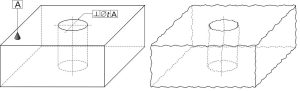
It is important to distinguish between datums (or features) and datums. The DRF is made up of points, planes, and axes (lines), or a combination of these components. The actual physical features of the DRF are called Datum features. They include holes, faces, slots and so on. On the part. They are not perfect. There is variation. These illustrations are intended to show that datum features (right and left) can be theoretical (perfect), but real (imperfect).
When defining a part, engineers will identify the most critical datum features. These are usually features that interface with other parts in the assembly. The part will be oriented to the datum frame if it has been referenced by the feature control frame (see Feature Control Framework).
A Feature of Size is any geometric shape that can be described by dimensions such as an angle, length or height. A datum, which can also be used to describe a Feature of Size, can also be used. When determining whether something is a Feature or not, you can use the caliper rule. If the tips of a measuring instrument can be placed around the part or inside the part and touch the surfaces, the feature is considered a Feature.
It is not a feature that size if you need to use the probe end to measure it. You can also apply tolerances to features of any size. When orientation tolerances are applied, they control the angle between the axis/midplane and the tolerance zone at a basic angle from a datum.
GD&T Basic Dimensions
The basic dimensions are mathematically precise numerical values that define the form, size and orientation of a part or feature. The basic dimensions are typically shown on a drawing enclosed within a box. However, they can also be invoked using a reference to a standard or a note on a drawing. Basic can also be applied to the CAD model.
Permissible deviations from the basic dimensions can be defined in the GD&T feature controls frame or by notes on a drawing. Basic dimensions are not subject to any default tolerances set out in the title block. Basic dimensions are often not used for quality inspection. Although basic dimensions can be measured, they don’t usually have any tolerance so they aren’t used for quality inspection purposes.
GD&T Symbols
GD&T, which is a feature-based system, means that all engineered parts are made up of features. Features are given geometric tolerances using feature control frames. These frames use a variety of symbols to indicate the tolerance. These Symbols, or Geometric Characteristics, are what people most often think of when they think about GD&T. Below is a list of symbols that can be used to represent some of these GD&T characteristics.
These symbols and characteristics fall under four main categories (or characteristics): form and orientation, location and runout.
Form tolerances are used to control the “shape” of features. They don’t require a reference datum.
Orientation tolerances are used to control the tilt of features. They are always associated with basic angles dimensions and can be used as a refinement for location. These feature control frames will always reference a datum due to their relative nature. If orientation tolerances are applied to surfaces, they will control form.
Location tolerances are used to control the location of a feature and are always associated in linear dimension. Location GD&T can locate a feature, or features of size based either on the feature or a series derived median points. These characteristics are extremely versatile and powerful and can control size, form and orientation within a single feature frame.
Material Condition Modifiers
When specifying geometric controls, it is often necessary to indicate that a tolerance applies for a feature at a specific feature size. Engineers can communicate their intent using the terms Maximum Material Condition and Least Material Condition.
These material condition modifiers can be used in a feature control framework following the tolerance. If the feature is not in the prescribed condition, the MMC or LMC modifiers can be applied to provide additional geometric tolerance. This is sometimes referred to as “bonus tolerance”.
Maximum Material Condition (MMC), – A condition in which the feature has the maximum amount of material within the specified limits. Ex: Largest pin/or smallest hole
Least Material Condition (LMC), – A condition in which the feature has the minimum material within the specified limits of size. (ex. smallest pin/or largest hole).
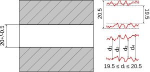
The MMC of the hole in the illustration is 19.5mm, and the LMC is 20.5mm. Another example is a set of holes sized to 20+/–0.5mm and with a tolerance of 0.6mm at MMC.
The illustration below shows that the MMC for the hole measures 19.5mm, and the LMC is 20.5mm. The MMC of the holes is 19.5mm in dia. If the holes are larger than their MMC, they have additional position tolerance equal the difference between their MMC sizes of 19.5mm and 20.5mm. The diameter tolerance for holes with diameters greater than 20.0mm is 1.1mm. This is the basis of the bonus tolerance concept.
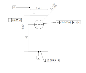
Frames for Feature Control
The requirements or instructions for the feature are stated in the feature control frames. So the feature control frames controls features. One message is contained in each feature control frame. If two messages are needed for a feature, then two feature control frames will be required.
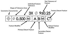
One of the geometric characteristic symbol is found in the first compartment of a feature frame. A feature control frame can only contain one of these symbols. Two requirements must be met for a feature to be considered a control frame. The symbol will indicate the type of control that is being applied to the feature.
The total tolerance for the feature is found in the second compartment of a feature-control frame. The tolerance for a feature is always a maximum tolerance, and never a plus or minus value.
The tolerance zone can be represented as a circle or diameter symbol (if it is preceded with a diameter symbol), this is commonly used to indicate the location of a hole. The default tolerance zone shape is parallel planes if there is no symbol preceding it. This is used often to place a profile or slot on a surface.
A material condition modifier such as Max Material Condition or Least Material Condition can be specified to modify a feature that is small, such as a hole, according to the feature tolerance. The default modifier for a feature of any size is RFS (Regardless Of Feature Size), but it is not included in this feature control frame. These modifiers are not allowed to be used for features that aren’t features of size (e.g. a plane surface).
If the feature control frames require them, the datum feature references will be stored in all remaining compartments. If a form tolerance is required, such as straightness or flatness, no datum reference will be allowed. If a tolerance for location, such as position, is specified, then the datum feature reference is usually provided.
The alphabetical order in which the datum references are listed is not important. Its significance is their order by precedence. Reading from left to right, they can be read as primary, secondary and tertiary. However, often Datum A will be the primary datum followed by B and then C for secondary and tertiary.
The primary feature is the first feature to be contacted (minimum contacts at 3 points), while the secondary feature is second (minimum contacts at 2 points), while the tertiary feature is third (minimum contacts at 1 point). The three datum features must be contacted simultaneously to establish the mutually perpendicular DRF. Datum Simulators are manufacturing, processing and inspection equipment such as a surfaceplate, a colet, a three jaw chuck, gage pin, and others that create the DRF.