In the world of computer-aided design (CAD) and CNC machining, CAD software plays a pivotal role in transforming design concepts into precise and intricate machine instructions. CAD software allows engineers, designers, and manufacturers to create detailed 2D and 3D models of their products, which are then used to generate toolpaths for CNC machines. These toolpaths guide the cutting tools and movements of the CNC machines, enabling the production of highly accurate and complex parts.
To achieve efficient CNC machining and optimize the production process, it is crucial to have a comprehensive understanding of the key features offered by CAD software. These features not only enhance design capabilities but also streamline the workflow, improve accuracy, and increase productivity. By familiarizing oneself with these features, designers and manufacturers can harness the full potential of CAD software, resulting in superior machining outcomes and reduced production costs.
Now, let’s delve into the eight must-know features of CAD software for CNC machining.
#1: 2D and 3D Modeling Capabilities
CAD software for CNC machining provides the essential capabilities of both 2D and 3D modeling. While 2D modeling involves creating detailed plans and technical drawings in two dimensions, 3D modeling adds an extra dimension, enabling designers to create three-dimensional virtual models of their parts or products. Both types of modeling have their significance in CNC machining.
In CNC machining, 2D modeling is often used to design simpler parts with basic geometries. It allows designers to define profiles, dimensions, and tolerances accurately. On the other hand, 3D modeling is indispensable when it comes to creating complex and intricate parts. It allows designers to visualize the part from different angles, inspect it for potential interferences or collisions, and analyze its functionality before it goes into production.
Accurate modeling is of utmost importance when it comes to designing complex parts for CNC machining. Here are some key benefits it brings:
- 3D modeling provides a realistic visual representation of the final product, helping designers and manufacturers to better understand its form, aesthetics, and functionality.
- Accurate modeling allows designers to identify and resolve any clashes or interferences between different components of the part. This prevents costly errors and ensures smoother production processes.
- CAD software enables precise measurement and dimensioning of the part, ensuring that it meets the required specifications and tolerances. This level of accuracy contributes to the overall quality of the final product.
- By utilizing accurate modeling, designers can easily make modifications, experiment with various design iterations, and evaluate their impact on the part’s performance without the need for physical prototyping.
- Accurate modeling reduces the need for trial and error during the machining process, leading to time and cost savings. By visualizing and optimizing the design upfront, potential issues can be identified and resolved early on, minimizing production delays and material wastage.
# 2: Parametric Modeling
Parametric modeling is a powerful feature offered by CAD software for CNC machining. It involves creating designs that are driven by parameters and relationships between different elements. In parametric modeling, the dimensions, constraints, and relationships of the design elements are defined using mathematical formulas and logical conditions. This allows for the creation of intelligent models that can be easily modified and updated based on changing design requirements.
With parametric modeling, designers can establish relationships between various components of a part or product. For example, they can link the size of one feature to another, ensuring that any changes made to one dimension automatically update all dependent dimensions.
Parametric modeling offers several advantages for CNC machining:
- Design Flexibility
- Time Efficiency
- Design Optimization
- Error Reduction
- Design Reusability
# 3: Compatibility with CNC Machines
CAD software for CNC machining supports various CNC machine formats to accommodate different machining requirements. Some common CNC machine formats supported by CAD software include:
- G-Code
- H-DXF/DWG
- STL
- STEP/IGES
Software compatibility with CNC machines is crucial when it comes to CNC machining. CNC machines come in various types and have specific capabilities and limitations. Software compatibility ensures that the CAD can communicate effectively with the CNC machine, utilizing its specific features to optimize the machining process. This includes considerations such as toolpath generation, machine code generation, and support for machine-specific functions.
#4: Toolpath Generation
CAD software utilizes various algorithms and techniques to generate toolpaths for CNC machining. The process typically involves the following steps:
- Geometry Analysis: The CAD software analyzes the 2D or 3D geometry of the part to be machined. It identifies the features, surfaces, and contours that need to be machined.
- Tool Selection: The software allows the user to select the appropriate cutting tools for the machining operation. This includes specifying the tool type, diameter, length, and other relevant parameters.
- Machining Strategy: The user defines the machining strategy, such as roughing, finishing, or contouring. The software takes this information into account to generate toolpaths that align with the selected strategy.
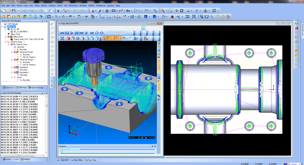
- Toolpath Generation: Based on the selected geometry, tooling, and machining strategy, the CAD software generates the toolpath. It calculates the tool’s movement, including cutting, retracting, and repositioning, to efficiently machine the part while considering factors like feed rates, cutting speeds, and tool angles.
- Simulation and Verification: The generated toolpaths can be simulated within the CAD software to visualize the machining process. This allows designers to verify the toolpath for any potential collisions, errors, or inconsistencies before sending it to the CNC machine.
#5: Simulation and Verification
Simulation and verification provide designers and engineers with a virtual environment to visualize and validate the machining process before it is executed.
Simulation allows users to identify potential errors or collisions that may occur during the machining process. By running a virtual simulation, designers can detect issues such as tool-path collisions, interference with clamps or fixtures, or unintended collisions between the tool and the workpiece. Identifying these errors beforehand helps prevent costly mistakes and ensures a smooth and error-free machining operation.
At the same time, simulation provides an opportunity to optimize machining processes for better efficiency and productivity. By analyzing the toolpaths, cutting strategies, and material removal rates, designers can identify areas of improvement and make necessary adjustments. This optimization can lead to reduced cycle times, improved surface finishes, and enhanced overall machining performance.
Lastly, simulation offers a visual representation of the entire machining operation, allowing designers to observe the tool’s movement, material removal, and chip formation. This visualization helps in understanding the sequence of operations, verifying the correctness of the toolpaths, and gaining insights into the machining process. It aids in better communication between designers and machinists, ensuring everyone is aligned on the intended manufacturing approach.
# 6: Material Library and Machining Data
CAD software for CNC machining often includes a material library, which contains a comprehensive database of various materials commonly used in manufacturing. This library provides designers and engineers with essential information about different materials, including their properties, such as density, thermal conductivity, hardness, and tensile strength.
Machining data within CAD software provides valuable information about tool selection and machining parameters that directly influence the CNC machining process. Here’s how this data aids in selecting appropriate tools and feeds:
- Tool Selection: The machining data includes recommended tool types, such as end mills, drills, or taps, for specific machining operations. It provides details about tool geometries, coatings, and cutting edge configurations optimized for various materials and machining strategies. By referring to the machining data, designers can choose the right tools that offer the desired cutting performance, tool life, and surface finish.
- Feeds and Speeds: Machining data encompasses feed rates, cutting speeds, and spindle speeds suitable for different materials and machining operations. This information helps designers determine the appropriate feed rates for achieving optimal chip formation, preventing tool wear or breakage, and ensuring efficient material removal. By utilizing the recommended feeds and speeds from the machining data, designers can enhance the machining process’s productivity, accuracy, and tool longevity.
- Process Optimization: Machining data also aids in process optimization by providing insights into parameters such as depth of cut, stepover, and tool engagement. Designers can analyze this data to fine-tune their machining strategies, minimizing cycle times, maximizing material removal rates, and improving overall process efficiency.
# 7: Integration with CAM Software
Integration between CAD and CAM software ensures a seamless transition from the design phase to the machining phase. It allows designers and engineers to directly transfer their design models, assemblies, and annotations from the CAD environment to the CAM environment. This eliminates the need for manual file conversions or rework, saving time and minimizing errors during the handover process.
By integrating CAD and CAM software, the design intent behind the part or component is preserved throughout the entire machining workflow. Any changes made in the CAD software automatically propagate to the CAM software, ensuring that the machining instructions align with the original design specifications. This synchronization eliminates discrepancies and ensures that the final machined part matches the intended design.
This feature also enables automatic toolpath generation based on the design model. CAM software utilizes the geometry and features defined in the CAD model to determine the most efficient toolpaths for machining operations such as roughing, finishing, and contouring. This automation eliminates the manual effort required to create toolpaths, reduces programming time, and improves consistency across machining processes.
# 8: Design Analysis and Optimization
CAD software offers various tools and functionalities to facilitate design analysis and optimization in CNC machining:
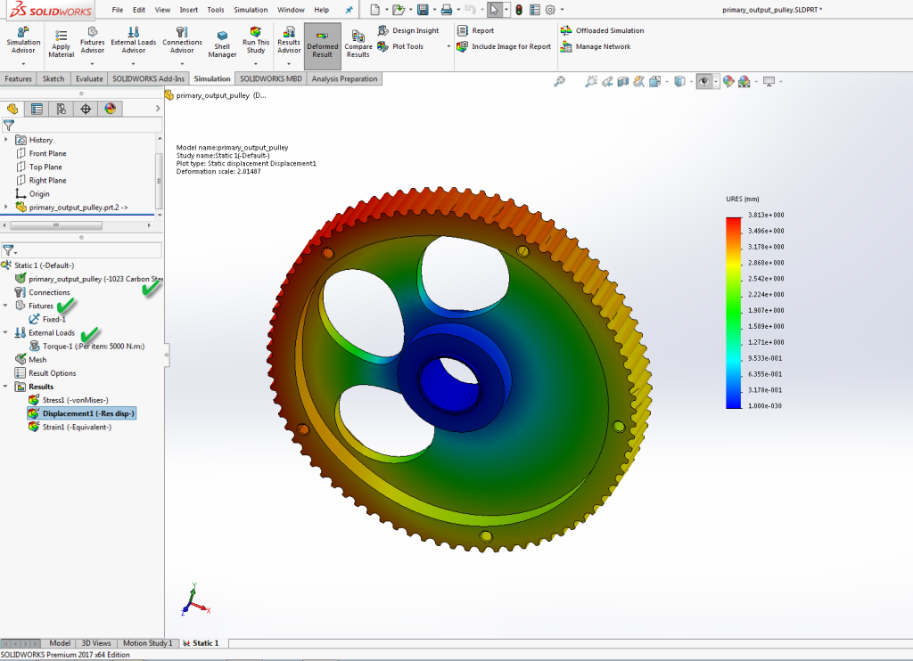
- Finite Element Analysis (FEA): CAD software often includes built-in FEA capabilities, allowing engineers to simulate and analyze the structural behavior of a design under different loading conditions. By defining material properties, boundary conditions, and applied loads, engineers can obtain detailed information about stress distribution, deformation, and factors of safety. This analysis helps identify potential design flaws and enables optimization for enhanced performance.
- Design Optimization Algorithms: CAD software may incorporate optimization algorithms that enable engineers to automatically optimize a design based on defined objectives and constraints. These algorithms can iterate through different design parameters to find an optimal solution that meets specified criteria, such as minimizing weight, maximizing stiffness, or reducing manufacturing costs. By leveraging these optimization tools, engineers can expedite the design refinement process and achieve superior performance outcomes.
- Integration with Simulation Tools: CAD software often integrates with specialized simulation tools that offer advanced analysis capabilities. These tools may include computational fluid dynamics (CFD), thermal analysis, or electromagnetic simulation. By seamlessly transferring the design geometry from CAD software to these simulation tools, engineers can perform in-depth analysis and optimization specific to their application requirements.
- Design Validation and Visualization: CAD software allows engineers to visualize analysis results in a 3D environment, providing a comprehensive understanding of the design’s behavior. This visualization aids in identifying critical areas, potential interferences, or areas of excessive stress. By visually inspecting the design, engineers can make informed decisions and further optimize the design for improved performance and manufacturability.