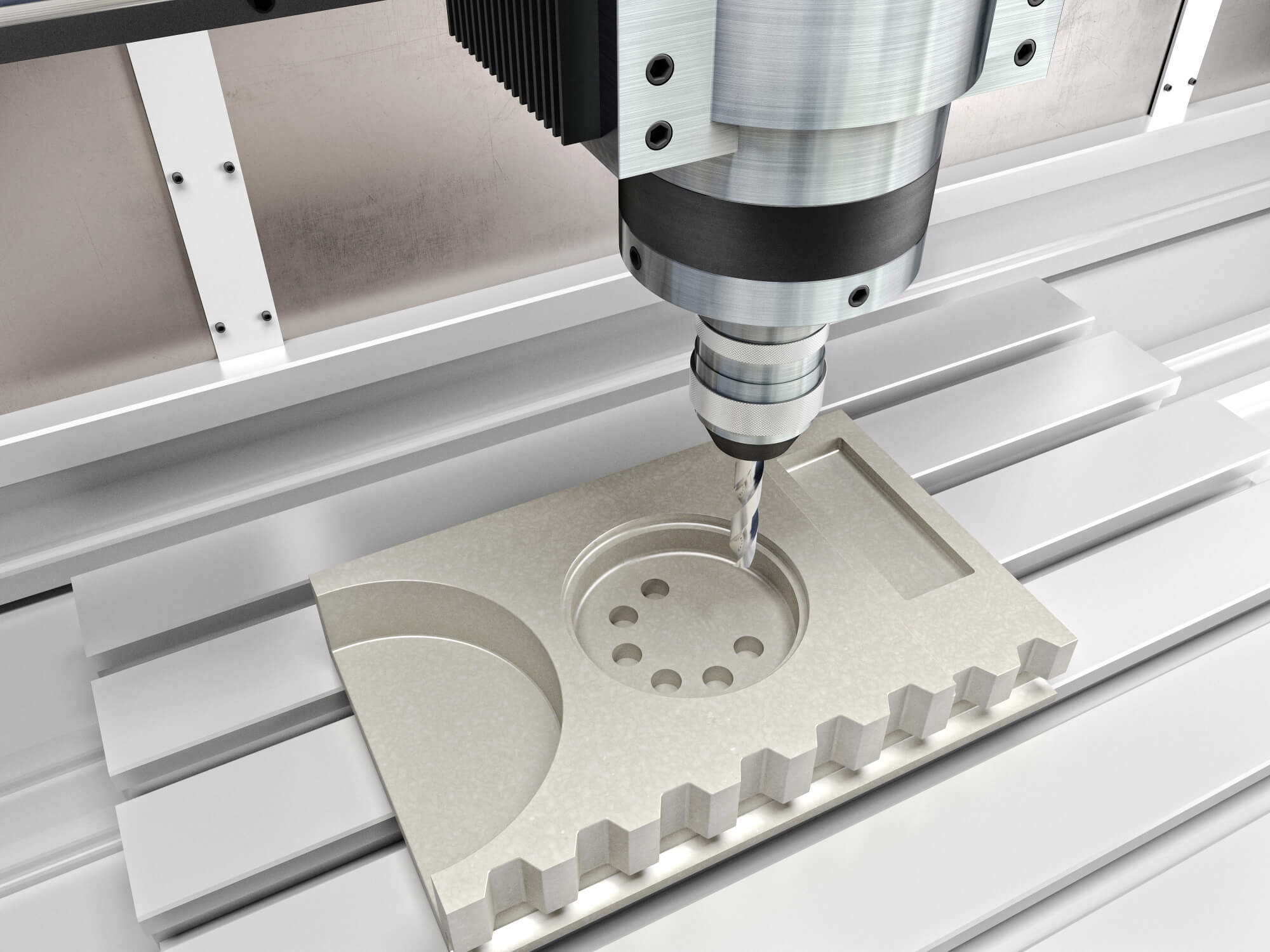
When it comes to CNC machining, precision is key. This precision hinges significantly on the proper use of units, whether metric or imperial. Each unit system has its own unique set of applications and understanding how to use them correctly is crucial for creating accurate and functional parts. Let’s delve into the intricacies of metric and imperial units, their conversions, and best practices for using them in CNC programming.
Coordinate Words and Their Role
In CNC programming, coordinates or “coordinate words” dictate the tool’s position at any given time. Common coordinate words include X, Y, Z, I, J, K, and R. These coordinates are the backbone of CNC programming, representing the dimensions required to precisely shape and size the workpiece.
Coordinate words rely on the unit system selected, which can be either metric (millimeters and meters) or imperial (inches and feet). The choice between these systems can affect how measurements are input and interpreted by the CNC machine.
Two Key Attributes of Dimensions
Dimensions in a CNC program have two main attributes:
- Unit System: This can be either metric or imperial.
- Reference Type: This can be absolute or incremental.
The metric system uses millimeters and meters, while the imperial system uses inches and feet. CNC dimensions must always be entered as decimal values rather than fractions. For example, 1/8 inch must be converted to 0.125 inches.
Using Metric and Imperial Units
Drawings and dimensions can be in either metric or imperial units. In the US, the imperial system is more common, while the metric system is prevalent in most other parts of the world. Many CNC machines equipped with Fanuc controllers can operate in either system. The initial unit system setting, known as the default state, is determined by the machine manufacturer or vendor but can be overridden by G-codes in the program.
Setting the Units
To set the units in a CNC program, you use specific G-codes at the beginning of the program:
- G20: Selects imperial units (inches and feet)
- G21: Selects metric units (millimeters and meters)
These codes are modal, meaning they remain in effect until another G-code changes them. Therefore, if G21 is used, the machine will stay in metric mode until G20 is introduced, and vice versa.
Pitfalls of Switching Units
Switching between metric and imperial units within the same program can lead to errors. All controllers, including Fanuc, are fundamentally based on the metric system due to its precision. When you switch from one unit system to another, the numerical values are adjusted without changing the fundamental measurements, which can result in inaccuracies. Consider these examples:
Example 1 – Switching from Metric to Imperial:
G21
G00 X60.0 (interpreted as 60 mm)
G20
After the switch, the value remains 60, but now it’s in inches, which incorrectly interprets 60 mm as 60 inches.
Example 2 – Switching from Imperial to Metric:
G20
G00 X6.0 (interpreted as 6 inches)
G21
Here, 6 inches incorrectly becomes 6 mm after the switch.
These examples highlight why it is crucial to stick to one unit system per program. If subprograms are used, they should also follow the same unit system to prevent conversion errors.
Best Practices for Using Units in CNC Programming
- Consistency: Always use the same unit system throughout a program. Avoid mixing metric and imperial units to prevent calculation errors.
- Clear Unit Definition: Specify the unit system at the beginning of the program using G20 or G21. Ensure this is done before any movement or coordinate commands.
- Avoid Unnecessary Switching: If a unit switch is necessary, it should be handled with care and tested thoroughly to ensure accuracy.
- Decimal Precision: Control the number of decimal places to match the precision required by the machining process. This helps in maintaining the accuracy of the parts.
- System Default Awareness: Be aware of the default unit system of the CNC machine, as it can influence the initial state upon startup.
Impact on Other CNC Functions
Changing units affects more than just the coordinates. It impacts various CNC functions, including:
- Coordinate Words: X, Y, Z, I, J, K increments, etc.
- Constant Surface Speed (CSS): Known as cutting speed in CNC lathes.
- Feed Rate Functions: Represented by F addresses.
- Offset Values: H and D offsets in milling, tool preset values in turning.
- Screen Position Display: Number of decimal places shown.
- Manual Pulse Generator (MPG): Scale values.
- Some Controller Parameters: Certain settings are tied to the unit system.
Comparison of Metric and Imperial Terms
Understanding the equivalent terms in both metric and imperial systems is essential for effective CNC programming. Here’s a quick reference table for common terms:
| Metric Term | Imperial Term |
|---|---|
| mm/min (MPM) | in/min (IPM or ipm) |
| mm/rev (mm/t) | in/rev (IPR or ipr) |
| kW | hp |
| mm | in |
| m | ft |
This table highlights how specific terms and units translate between the two systems, facilitating better understanding and conversion where necessary.
Mastering these guidelines and the differences between metric and imperial units will enhance the precision and efficiency of your CNC machining.
Other Articles You Might Enjoy
- Precision CNC Machining of Steel: High-Volume Production
Precision CNC Machining and High-Volume Production As an integral part of modern manufacturing processes, Precision Computer Numerical Control (CNC) machining brings about unmatched accuracy and consistency in the production of…
- Diving into Vertical CNC Machining Centers: From Programming to Specifications
When you step into a machine shop, the hum of CNC machines is a familiar sound. Among these, the vertical CNC machining center is a workhorse, particularly when it comes…
- Material Versatility in CNC Machining: From Titanium to Thermoplastics
Introduction to CNC Machining CNC machining stands as a cornerstone in the manufacturing sector, enabling the precise creation of parts and components. This process utilizes computer numerical control (CNC) to…
- Precision CNC Machining for High-Performance Industrial Machinery
Precision CNC Machining for High-Performance Industrial Machinery The process of Precision CNC (Computer Numerical Control) machining is at the core of manufacturing high-performance industrial machinery. This technique leverages a computer's…
- Nickel vs. Cobalt Alloys in High-Temperature CNC Machining: A Detailed Analysis?
Nickel and Cobalt Alloys in High-Temperature CNC Machining Both Nickel and Cobalt alloys play an essential role in high-temperature CNC machining. These metal alloys are popular choices due to their…
- CNC Machining for Medical Applications: Compliance and Material Selection?
Introduction to CNC Machining in Medical Applications CNC or Computer Numerical Control machining is a manufacturing process wherein pre-programmed computer software dictates the movement of factory tools and machinery. This…


