In the fast-paced world of CNC machining, carbide inserts are the cornerstone of precision and efficiency, transforming digital designs into high-quality components for industries like aerospace, automotive, and medical manufacturing. These indexable carbide inserts serve as the critical cutting edge in CNC machines, enabling high-speed, high-precision material removal. With thousands of shapes, grades, coatings, and geometries available, selecting the right carbide inserts can be challenging. This comprehensive guide simplifies the process, providing a systematic framework for choosing carbide inserts, best practices for their application, an expanded troubleshooting guide, and a forward-looking perspective on carbide cutting tool innovations. By mastering carbide inserts, machinists and engineers can boost productivity, enhance part quality, and reduce costs in CNC machining operations.
Understanding Carbide Inserts: The Heart of CNC Machining
Defining Carbide Inserts: Precision CNC Cutting Tools
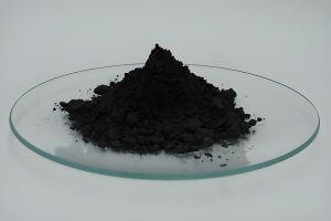
Carbide inserts are replaceable, indexable carbide inserts mounted in a tool holder, acting as the primary cutting edge in CNC machining. Composed of tungsten carbide—a robust ceramic-metal composite—these carbide inserts are produced via powder metallurgy, blending fine tungsten carbide powder with a cobalt binder and sintering at ~1,500°C. This process creates tungsten carbide inserts with exceptional hardness, heat resistance, and wear resistance, making them ideal for demanding CNC machining applications.
Unlike High-Speed Steel (HSS), carbide inserts offer superior hardness (90–94 HRA vs. 62–64 HRA), enabling cutting speeds 4–12 times faster (e.g., 500 SFM vs. 100 SFM in steel). Their indexable design allows operators to rotate to a fresh edge, minimizing downtime and costs. In precision-driven industries, carbide inserts deliver tighter tolerances (e.g., ±0.0005″ in aerospace) and finer surface finishes (32–63 microinches vs. 63–125 for HSS), cementing their role as essential CNC machining tools.
The Ultimate Selection Guide: Choosing the Perfect Carbide Inserts
Selecting the optimal carbide inserts requires a deep understanding of their specifications and alignment with specific machining needs. This involves decoding standards, matching grades to materials, selecting coatings, and choosing geometries tailored to the operation.
Decoding ISO & ANSI Insert Codes
Every carbide insert carries a standardized code (e.g., CNMG 432 in ANSI or CNMG 120408 in ISO), detailing its shape, size, and features. For example, CNMG 432 translates to:
- C: 80° diamond shape.
- N: 0° clearance angle (negative rake, double-sided).
- M: Standard tolerance.
- G: Cylindrical hole with chipbreakers.
- 4: 1/2″ inscribed circle (IC).
- 3: 3/16″ thickness.
- 2: 1/32″ nose radius.
ISO codes use metric measurements (e.g., 12 mm edge length, 0.8 mm radius). Mastering these codes ensures machinists select carbide inserts that align with CNC machining requirements, enhancing precision and efficiency.
Matching Grades to Materials: The ISO P-M-K System
The grade of a carbide insert defines its substrate and coating, optimized for specific workpiece materials. The ISO system categorizes grades into six groups:
- P (Blue): Steels (carbon, alloy).
- M (Yellow): Stainless steels.
- K (Red): Cast irons.
- N (Green): Non-ferrous metals (e.g., aluminum).
- S (Orange): Superalloys (e.g., titanium, Inconel).
- H (Grey): Hardened materials (>45 HRC).
Each group includes numerical designations (01–50), with lower numbers (e.g., P10) favoring wear resistance for finishing and higher numbers (e.g., P40) prioritizing toughness for roughing. Selecting the appropriate grade ensures carbide inserts maximize performance in CNC machining.Table 1: ISO Carbide Insert Grade Applications
| ISO Code | Material Group | Grade Range | Applications |
| P (Blue) | Steels | P01–P50 | P01–P15: Finishing; P20–P35: General; P40–P50: Roughing |
| M (Yellow) | Stainless Steels | M10–M40 | M10–M20: Finishing; M25–M35: General; M40: Roughing |
| K (Red) | Cast Irons | K01–K30 | K01–K10: Finishing; K15–K25: General; K30: Roughing |
| N (Green) | Non-Ferrous | N01–N30 | N01–N10: High-speed finishing; N15–N30: General |
| S (Orange) | Superalloys | S10–S40 | S10–S20: Finishing; S25–S40: Roughing |
| H (Grey) | Hardened Materials | H01–H30 | H01–H10: Finishing; H15–H30: Semi-finishing |
Analysis: The table highlights the versatility of carbide inserts across material groups. For instance, P-grade carbide inserts are widely used for steels due to their prevalence in manufacturing, with P20–P35 grades being the most versatile for general-purpose machining. N-grade carbide inserts, often uncoated, excel in aluminum due to their polished surfaces, preventing material adhesion. Selecting the right grade is critical to balancing wear resistance and toughness, directly impacting carbide insert longevity and part quality.
Choosing the Right Coating
Coatings on carbide inserts enhance durability by reducing friction and heat. Common coatings include:
- TiN (Titanium Nitride): General-purpose for steels, recognizable by its gold color.
- TiCN (Titanium Carbonitride): Hard and wear-resistant for abrasive materials like cast iron.
- TiAlN/AlTiN: Heat-resistant for high-speed machining of steels and superalloys.
- Nanocomposite: Ultra-hard for extreme applications like hardened steels (>60 HRC).
CVD coatings are ideal for continuous cuts, while PVD coatings suit interrupted cuts and sticky materials. For aluminum, polished or DLC-coated carbide inserts prevent built-up edge (BUE).
Table 2: Carbide Insert Coating Comparison
| Coating | Hardness (GPa) | Max Temp (°C) | Best Applications | Avoid On |
| TiN | ~24 | ~600 | General-purpose steels | Superalloys |
| TiCN | ~32 | ~400 | Cast iron, aluminum | High-heat cuts |
| TiAlN | ~28–35 | ~700–800 | High-speed steel, stainless | Aluminum |
| AlTiN | ~38–45 | ~800–900 | Hardened steels, titanium | Aluminum |
| Nanocomposite | ~35–45+ | ~900–1200 | Hardened steels, superalloys | Aluminum |
Analysis: The table shows that carbide inserts with AlTiN and nanocomposite coatings are preferred for high-temperature applications due to their superior heat resistance, enabling dry or minimal-coolant machining. TiCN-coated carbide inserts are cost-effective for abrasive materials but require robust cooling. Avoiding TiAlN/AlTiN on aluminum is critical to prevent BUE, ensuring carbide insert performance.
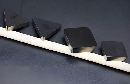
Geometry and Chipbreakers
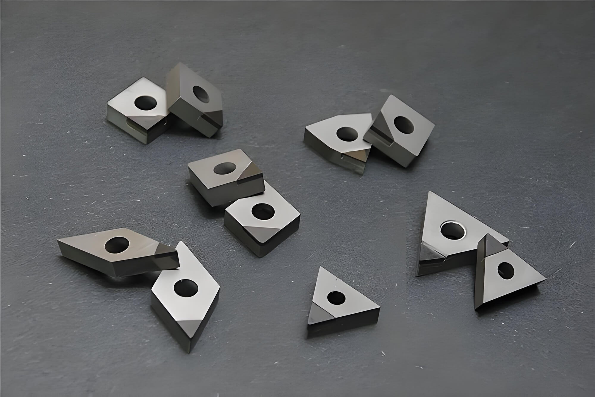
The geometry of carbide inserts balances strength and versatility:
- Round (R): Strongest, ideal for heavy roughing.
- Square (S): Robust for general machining.
- Diamond (C, D, V): Versatile for profiling and finishing.
Nose Radius: Larger radii (e.g., 0.8 mm) enhance strength but increase cutting forces; smaller radii (e.g., 0.2 mm) improve surface finish.
Rake Angle: Negative rake carbide inserts (e.g., CNMG) are durable for roughing; positive rake carbide inserts (e.g., CCMT) reduce forces for finishing.
Chipbreakers: Grooves on carbide inserts control chip flow, optimized for finishing, medium, or roughing operations.
Table 3: Carbide Insert Geometry Selection
| Shape | Strength | Applications | Best for Machine Rigidity |
| Round (R) | Highest | Heavy roughing | High |
| Square (S) | High | General-purpose | High–Moderate |
| 80° Diamond (C) | Moderate | Profiling, medium cuts | Moderate |
| 55° Diamond (D) | Lower | Finishing, profiling | Moderate–Low |
| 35° Diamond (V) | Lowest | Fine finishing | Low |
Analysis: The table illustrates that carbide insert shape selection depends on the machining operation and machine rigidity. Round carbide inserts are the go-to for heavy roughing on rigid CNC machines, while diamond-shaped carbide inserts (e.g., V) are suited for low-rigidity setups requiring fine finishes. Matching geometry to the machine’s capabilities ensures stable CNC machining performance.
Best Practices for Carbide Insert Performance
To unlock the full potential of carbide inserts, adhere to these best practices:
- Optimize Speeds and Feeds: Use manufacturer data for cutting speed (SFM), feed rate (IPR), and depth of cut (DOC). Adjust based on chip color (e.g., brown for steel) and carbide insert wear patterns.
- Ensure Rigidity: Minimize tool overhang to prevent vibration, a primary cause of carbide insert failure.
- Coolant Strategy: Use high-pressure coolant for continuous cuts; avoid it in interrupted cuts to prevent thermal shock in carbide inserts.
- Proactive Indexing: Rotate carbide inserts before excessive wear to maintain part quality.
- Proper Storage: Store carbide inserts in protective packaging to protect delicate edges.
These practices enhance carbide insert longevity and CNC machining efficiency.
Diagnosing and Fixing Carbide Insert Failures
Analyzing carbide insert wear provides critical insights for process optimization. The ideal wear is gradual flank wear; other failures signal process issues. The following table outlines common carbide insert failures and solutions.Table 4: Carbide Insert Failure Analysis
| Failure Mode | Appearance | Causes | Corrective Actions |
| Flank Wear | Uniform wear on flank | Normal abrasion | Use wear-resistant carbide inserts (e.g., Al₂O₃ coating). |
| Crater Wear | Cavity on rake face | Excessive heat | Lower speed, use heat-resistant carbide inserts (CVD). |
| Chipping | Edge breakage | Vibration, high feed | Improve rigidity, select tougher carbide inserts. |
| Built-Up Edge | Material welded to edge | Low temperature, gummy materials | Increase speed, use polished carbide inserts for aluminum. |
| Thermal Cracking | Cracks perpendicular to edge | Thermal shock in interrupted cuts | Run dry, use shock-resistant carbide inserts. |
Analysis: The table shows that carbide insert failures are often linked to improper parameters or setup. For example, chipping in carbide inserts frequently results from vibration, which can be mitigated by reducing tool overhang or selecting tougher grades. Built-up edge is common in aluminum machining but can be prevented with polished carbide inserts, highlighting the importance of material-specific selections.
Optimizing Carbide Insert Performance by Material
Different workpiece materials require tailored carbide insert selections and parameters. The following table provides recommended settings for common materials.Table 5: Carbide Insert Parameters by Material
| Material | ISO Grade | Coating | Speed (SFM) | Feed (IPR) | DOC (in) |
| Carbon Steel | P20–P35 | TiAlN/CVD | 400–600 | 0.008–0.015 | 0.040–0.120 |
| Stainless Steel | M25–M35 | PVD | 200–400 | 0.006–0.012 | 0.030–0.100 |
| Cast Iron | K15–K25 | TiCN | 300–500 | 0.010–0.018 | 0.050–0.150 |
| Aluminum | N01–N10 | Polished/DLC | 800–2000 | 0.004–0.010 | 0.020–0.080 |
| Titanium | S25–S40 | AlTiN | 100–200 | 0.004–0.008 | 0.020–0.060 |
Analysis: The table demonstrates how carbide insert parameters vary by material. High-speed aluminum machining benefits from polished carbide inserts and aggressive speeds (up to 2000 SFM), while titanium requires slower speeds and tougher carbide inserts to handle its heat-resistant properties. These tailored settings optimize carbide insert performance and tool life.
The Future of Carbide Inserts: Smart and Sustainable
Carbide inserts are evolving with Industry 4.0, integrating digital and sustainable technologies:
- Smart Inserts: Sensors embedded in carbide inserts monitor temperature and vibration, enabling predictive maintenance and adaptive control for optimized CNC machining.
- Advanced Substrates: New ceramics and nanocomposites enhance carbide insert durability for superalloys and hardened steels.
- Recycling Programs: Recycling used carbide inserts recovers tungsten and cobalt, reducing waste and supporting a circular economy.
These innovations position carbide inserts as intelligent, sustainable components in modern CNC machining.
Mastering CNC Machining with Carbide Inserts
Carbide inserts are the backbone of high-performance CNC machining, combining material science with precision engineering. By decoding ISO/ANSI codes, matching grades and coatings to materials, and optimizing geometries, you can achieve superior efficiency and part quality. Leverage failure analysis and material-specific parameters to refine your process, and embrace innovations like smart carbide inserts to stay competitive. Ready to elevate your CNC machining? Visit want.net for expert carbide insert selection guides or contact our team for tailored CNC machining solutions.
FAQ:
1. What are carbide inserts, and why are they critical in CNC machining?
Answer: Carbide inserts are replaceable, indexable cutting tools made from tungsten carbide, a durable ceramic-metal composite, used as the primary cutting edge in CNC machining. Produced via powder metallurgy at ~1,500°C, carbide inserts offer exceptional hardness (90–94 HRA) and heat resistance, enabling cutting speeds 4–12 times faster than High-Speed Steel (HSS) (e.g., 500 SFM vs. 100 SFM in steel). Their indexable design reduces downtime, while their precision delivers tight tolerances (±0.0005″) and superior surface finishes (32–63 microinches), making them essential CNC machining tools for industries like aerospace and medical.
2. How do I choose the right carbide insert for my workpiece material?
Answer: Select carbide inserts using the ISO P-M-K system to match the material: Steel: P-grade carbide inserts (e.g., P20–P35, TiAlN coating) for general machining.
Stainless Steel: M-grade carbide inserts (e.g., M25–M35, PVD coating) for sticky materials.
Aluminum: N-grade carbide inserts (e.g., N01–N10, polished or DLC coating) to prevent built-up edge (BUE).
Superalloys: S-grade carbide inserts (e.g., S25–S40, AlTiN coating) for titanium or Inconel.
Choosing the correct grade and coating extends carbide insert life and enhances CNC machining performance.
3. What is the role of coatings on carbide inserts, and which is best for my needs?
Answer: Coatings on carbide inserts reduce friction and heat, improving wear and heat resistance. Common coatings include: TiN (Titanium Nitride): Cost-effective for general steel machining.
TiCN (Titanium Carbonitride): Ideal for abrasive materials like cast iron and high-silicon aluminum.
TiAlN/AlTiN: Heat-resistant for high-speed machining of steels and superalloys.
Nanocomposite: Ultra-hard for extreme applications like hardened steels (>60 HRC).
For aluminum, use polished carbide inserts to avoid BUE; for high-temperature alloys, AlTiN-coated carbide inserts excel. Match the coating to your material and cutting conditions.
4. How do I read the ISO/ANSI codes on carbide inserts?
Answer: Carbide insert codes (e.g., CNMG 432 in ANSI or CNMG 120408 in ISO) describe shape, size, and features. For CNMG 432: C: 80° diamond shape; N: 0° clearance angle (negative rake); M: standard tolerance; G: hole with chipbreakers.
4: 1/2″ inscribed circle; 3: 3/16″ thickness; 2: 1/32″ nose radius.
ISO codes use metric units (e.g., 12 mm edge length). Understanding these codes helps select carbide inserts suited for specific CNC machining tasks.
5. How does the geometry of carbide inserts affect machining performance?
Answer: The geometry of carbide inserts balances strength and versatility: Round (R): Strongest, ideal for heavy roughing on rigid machines.
Square (S): Robust for general-purpose machining.
Diamond (C/D/V): Versatile for profiling and finishing, with V-shape best for fine work.
Nose Radius: Larger radii (e.g., 0.8 mm) increase strength but risk vibration; smaller radii (e.g., 0.2 mm) enhance surface finish. Positive rake carbide inserts (e.g., CCMT) reduce cutting forces for finishing, while negative rake carbide inserts (e.g., CNMG) are durable for roughing. Match geometry to operation and machine rigidity.
6. How can I optimize carbide insert performance using chip and wear analysis?
Answer: Analyzing chip color and carbide insert wear optimizes CNC machining: Chip Color: Brown or straw-colored chips in steel indicate optimal temperatures; blue chips show effective heat transfer to the chip.
Wear Patterns: Uniform flank wear is ideal; crater wear suggests excessive heat, requiring slower speeds or heat-resistant carbide inserts; chipping indicates vibration, needing better rigidity or tougher carbide inserts.
Adjust speed, feed, and coolant based on these indicators to extend carbide insert life.
Reference:
https://www.linkedin.com/pulse/top-10-applications-carbide-inserts-modern-industries-brjqc