Introduction: The Power of Carbide End Mills in CNC Machining
In the realm of Computer Numerical Control (CNC) machining, the carbide end mill stands as the cornerstone of precision, efficiency, and versatility. These advanced tools are indispensable for cutting challenging materials, from aerospace-grade titanium alloys to high-volume automotive steel components. The carbide end mill directly influences product quality, production speed, and manufacturing costs, making it a pivotal choice for machining professionals. This comprehensive guide equips manufacturing engineers, CNC shop managers, and technicians with an in-depth understanding of carbide end mills, covering their material science, geometric design, coating technologies, cutting parameter optimization, troubleshooting strategies, and emerging trends. By mastering the carbide end mill, professionals can achieve superior machining outcomes and maintain a competitive edge in precision manufacturing. Whether you’re optimizing high-speed production or tackling complex 3D contours, the carbide end mill is your key to unlocking CNC potential.
Part 1: Deconstructing the High-Performance Carbide End Mill
To fully leverage the capabilities of a carbide end mill, one must first grasp its fundamental composition and design principles. This section dissects the material science and geometric intricacies that define the performance of carbide end mills, providing a solid foundation for their strategic application.
1.1 Material Science: The Core of Carbide End Mills
The term “solid carbide,” often used in marketing, refers to cemented carbide—a metal-matrix composite that powers the carbide end mill’s exceptional performance. Understanding its composition is critical for selecting the right carbide end mill for specific machining tasks.
1.1.1 Composition Breakdown
Carbide end mills are primarily composed of two key materials:
- Tungsten Carbide (WC) Grains: These hard grains provide the carbide end mill with unparalleled hardness (90–94 HRA), wear resistance, and thermal stability, enabling it to cut through tough materials like stainless steel and titanium with precision.
- Cobalt (Co) Binder: Acting as a metallic glue, cobalt binds the brittle tungsten carbide grains, imparting toughness to the carbide end mill. This prevents fracturing during high-impact cuts, ensuring durability in demanding applications.
1.1.2 Microstructure and Performance
The performance of a carbide end mill hinges on the size and distribution of its tungsten carbide grains. Smaller grains, often classified as sub-micron or ultra-fine (0.2–0.8 µm), allow for denser packing during sintering, reducing the reliance on the softer cobalt binder. This results in a harder, more wear-resistant carbide end mill capable of maintaining a sharp cutting edge for precision machining. High-performance carbide end mills typically use sub-micron grains for applications like high-speed finishing or micro-milling.
The balance between hardness and toughness is a critical engineering trade-off in carbide end mills. A higher cobalt content (8–12%) enhances toughness, making the carbide end mill more resistant to chipping in interrupted cuts or low-rigidity setups. Conversely, a lower cobalt content (4–6%) maximizes hardness and wear resistance, ideal for abrasive materials but increasing brittleness. Manufacturers design carbide end mills with specific cobalt ratios tailored to applications, such as roughing tough alloys or finishing delicate surfaces, ensuring optimal performance for diverse CNC machining scenarios.
1.1.3 Manufacturing Considerations
The production of a carbide end mill involves sintering tungsten carbide and cobalt into a solid rod, followed by precision grinding. The quality of the raw materials, sintering process, and grinding accuracy directly impact the carbide end mill’s performance. High-end carbide end mills often use premium-grade carbide with consistent grain size and minimal impurities, ensuring reliability in high-stakes applications like aerospace component manufacturing.
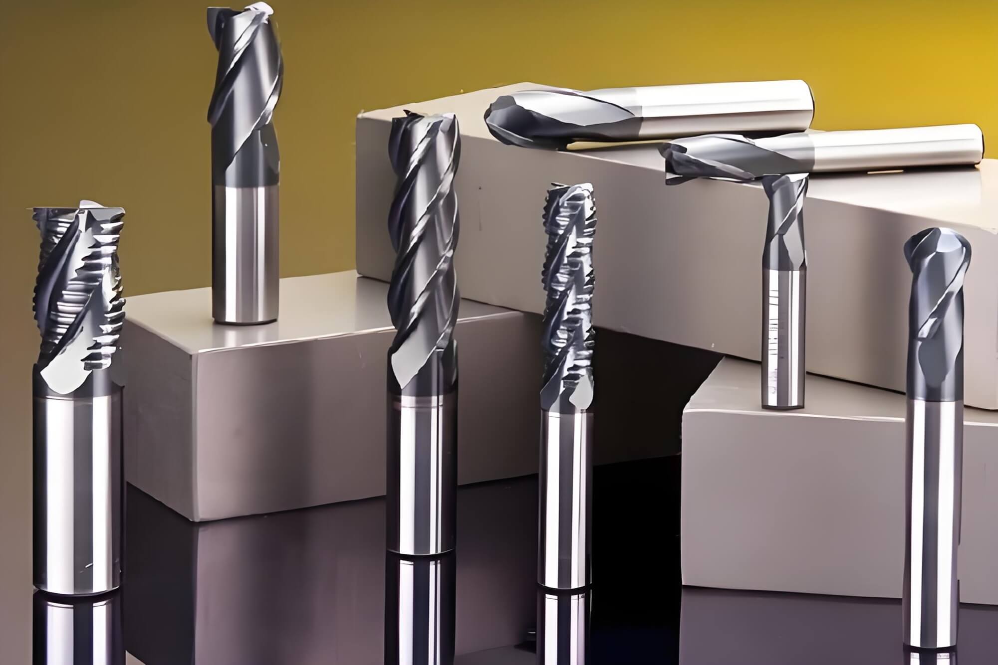
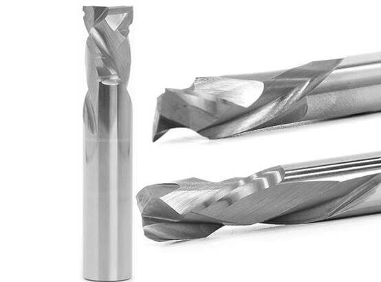
1.2 Geometry: The Language of Precision
The geometry of a carbide end mill is a meticulously engineered system designed to optimize cutting forces, chip evacuation, and heat dissipation. Each feature of a carbide end mill’s geometry serves a specific purpose, influencing its suitability for various materials and operations.
Flutes and Chip Evacuation:
- 2-Flute Carbide End Mills: These provide maximum chip clearance, ideal for soft materials like aluminum and plastics that produce long, stringy chips. They are often center-cutting, enabling plunging operations in CNC machining.
- 3-Flute Carbide End Mills: Offering a balance of strength and chip evacuation, these are versatile for slotting and profiling in both ferrous and non-ferrous metals.
- 4-Flute and Higher: These carbide end mills have a larger core diameter, enhancing rigidity and enabling faster feed rates. They produce superior surface finishes due to lighter chip loads, making them ideal for hard materials like steel and titanium.
Helix Angle and Cutting Dynamics:
Low Helix Angle (15°–35°): A slower spiral strengthens the cutting edge of a carbide end mill, suitable for roughing hard or tough materials. However, it may reduce chip evacuation efficiency and increase chatter risk.
High Helix Angle (38°–60°): A faster spiral promotes aggressive shearing, reducing tool deflection and improving chip evacuation in soft materials like aluminum. However, it weakens the cutting edge of the carbide end mill.
Variable Helix: Advanced carbide end mills feature varying helix angles to disrupt harmonic vibrations, suppressing chatter and enabling high-speed, stable machining.
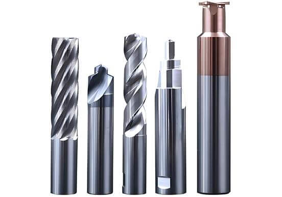
End Geometry:
Square End Carbide End Mills: Designed for general-purpose milling, slotting, and profiling, these produce flat bottoms and sharp corners.
Ball Nose Carbide End Mills: Featuring a hemispherical tip, these are ideal for 3D contouring, surfacing, and milling fillets for smooth, complex surfaces.
Corner Radius Carbide End Mills: These strengthen corners with a radius transition, reducing chipping in heavy cuts or hard materials, making them a staple in high-performance CNC machining.
Additional Geometric Features:
Core Diameter: A larger core in multi-flute carbide end mills enhances rigidity, critical for machining hard materials.
Rake Angles: Positive rake angles reduce cutting forces in soft materials, while negative rake angles strengthen edges for hard, brittle materials.
Variable Pitch: Unequal flute spacing in carbide end mills minimizes vibrations, improving stability and surface finish.
1.3 Manufacturing Process of Carbide End Mills
Carbide end mills are crafted from pre-sintered carbide rods through a sophisticated process:
- Blank Preparation: High-quality, micro-grain carbide rods are selected, determining the carbide end mill’s shank diameter and length.
- Laser Marking: Part numbers are etched for traceability.
- CNC Grinding: Multi-axis CNC grinders with diamond wheels shape the carbide end mill’s flutes, helix angles, and tip geometry with precision.
- Cooling and Lubrication: High-pressure coolant ensures tight tolerances and a smooth finish during grinding.
- Coating Application: Physical Vapor Deposition (PVD) or Chemical Vapor Deposition (CVD) coatings enhance the carbide end mill’s performance (see Part 4).
Complex geometries, such as variable helix or pitch, require advanced CNC grinders, increasing production costs but delivering superior performance in high-end carbide end mills.
Part 2: Carbide End Mills vs. High-Speed Steel (HSS)
This section compares carbide end mills with HSS tools, providing a data-driven guide for strategic tool selection in CNC machining.
2.1 Performance Metrics
Hardness and Wear Resistance: Carbide end mills (90–94 HRA) significantly outperform HSS (62–64 HRA), maintaining sharp edges longer, especially in abrasive or hardened materials.
Toughness: HSS is tougher, absorbing shock better in low-rigidity setups or interrupted cuts, while carbide end mills are more brittle, prone to chipping under vibration.
Heat Resistance: Carbide end mills excel at high temperatures, supporting cutting speeds 2–4 times faster than HSS (e.g., 500 SFM vs. 100 SFM in steel), driving productivity in high-speed CNC machining.
2.2 Economic Analysis
Carbide end mills cost 3–5 times more than HSS tools but offer a lower cost-per-part due to:
- Longer Tool Life: Carbide end mills require fewer replacements.
- Higher Efficiency: Faster cutting speeds reduce cycle times.
- Reduced Downtime: Less frequent tool changes enhance productivity.
HSS tools remain viable for hobbyists, small-batch production, or low-speed machines, where their lower cost and toughness outweigh the advantages of carbide end mills.
2.3 Practical Identification
Weight: Carbide end mills are denser, feeling roughly twice as heavy as HSS tools of the same size.
Appearance: Carbide end mills have a darker gray body with glossy shanks; HSS tools are brighter with matte shanks.
Magnetism: Carbide end mills are weakly magnetic due to cobalt; HSS is strongly magnetic.
Wear Patterns: Worn carbide end mills show chipping; HSS tools exhibit dulling or burn marks.
Table 1: Carbide End Mills vs. HSS Comparison
| Feature | Carbide End Mill | High-Speed Steel (HSS) |
| Material Composition | Tungsten Carbide + Cobalt | Iron-based alloy (W, Mo, Cr, V) |
| Hardness (HRA) | 90–94 | 62–64 |
| Toughness | Lower (brittle) | Higher (forgiving) |
| Max Cutting Speed (SFM) | 500+ (steel) | ~100 (steel) |
| Heat Resistance | Excellent | Good, softens at lower temps |
| Cost | High (3–5x HSS) | Low |
| Tool Life | Long | Shorter |
| Applications | High-volume, hard materials | General purpose, soft materials |
| Failure Mode | Chipping, fracture | Dulling, edge rounding |
2.4 Case Study: Carbide vs. HSS in Production
In a high-volume steel machining operation, a carbide end mill reduced cycle time by 40% compared to an HSS tool, cutting at 500 SFM versus 100 SFM. Despite a higher initial cost, the carbide end mill’s extended tool life and reduced downtime lowered the cost-per-part by 25%, demonstrating its value in industrial CNC settings.
Part 3: Strategic Selection of Carbide End Mills
Selecting the right carbide end mill involves matching its features to the workpiece material, machining operation, and machine capabilities.
3.1 Material-Based Selection
Aluminum and Non-Ferrous Alloys:
- Challenge: Long, sticky chips prone to built-up edge (BUE).
- Solution: 2–3 flute carbide end mills with high helix angles (45°+) and polished or lubricious coatings (ZrN, TiB2, DLC). Avoid AlTiN coatings due to aluminum affinity.
Low-Carbon and Alloy Steels:
- Challenge: High cutting forces and heat generation.
- Solution: 4+ flute carbide end mills with medium (35–40°) or variable helix and corner radius. Use AlTiN or AlCrN coatings for heat resistance.
Stainless Steels:
- Challenge: Work-hardening, poor thermal conductivity.
- Solution: 3–5 flute carbide end mills with variable helix and positive rake. AlTiN Nano or AlCrN coatings with coolant are ideal.
Titanium and Superalloys (e.g., Inconel):
- Challenge: Extreme heat, chemical reactivity.
- Solution: 3–5 flute carbide end mills with low helix, robust core, and corner radius. AlTiN Nano coatings handle high temperatures.
3.2 Operation-Based Selection
Roughing: Use serrated or 2–3 flute carbide end mills to maximize material removal rates (MRR).
Finishing: 4+ flute carbide end mills with high helix angles ensure smooth surfaces and tight tolerances.
Slotting: 2–3 flute carbide end mills prevent chip packing in full-width cuts.
Profiling: 4+ flute carbide end mills support high feed rates and superior finishes in side milling.
3.3 Machine Rigidity and Spindle Capability
The performance of a carbide end mill is limited by the CNC machine’s rigidity and spindle speed. High-performance carbide end mills require rigid setups to prevent chatter and leverage their high-speed capabilities. A loose tool holder or low-power machine can cause chipping or premature wear, negating the benefits of an advanced carbide end mill.
3.4 Practical Selection Tips
Consult manufacturer catalogs for material-specific recommendations.
Test carbide end mills in small batches to validate performance.
Invest in rigid tool holders (e.g., hydraulic or shrink-fit) to maximize the potential of carbide end mills.
Table 2: Carbide End Mill Selection Matrix
| Material | Roughing | Finishing | Slotting |
| Aluminum Alloys | 2–3 Flute, High Helix, ZrN/DLC | 3 Flute, High Helix, ZrN/DLC | 2 Flute, High Helix, ZrN/DLC |
| Low Carbon Steel | 3–4 Flute, Med Helix, AlTiN | 4–6 Flute, Var Helix, AlTiN | 3 Flute, Med Helix, AlTiN |
| Tool Steel | 4–5 Flute, Low Helix, AlTiN Nano | 5–7 Flute, Var Helix, AlTiN Nano | 4 Flute, Low Helix, AlTiN Nano |
| Stainless Steel | 3–4 Flute, Var Helix, AlTiN Nano | 4–5 Flute, Var Helix, AlTiN Nano | 3 Flute, Var Helix, AlTiN Nano |
| Titanium/Superalloys | 3–4 Flute, Low Helix, AlTiN Nano | 4–5 Flute, Var Helix, AlTiN Nano | 3–4 Flute, Low Helix, AlTiN Nano |
Part 4: Surface Science of Carbide End Mill Coatings
Coatings are critical to the performance of carbide end mills, enhancing hardness, reducing friction, and providing thermal protection.
4.1 Role of Coatings
Hardness and Wear Resistance: Coatings protect the carbide end mill’s substrate from abrasive wear.
Lubricity: Low-friction coatings prevent BUE and reduce heat.
Thermal Barrier: High-temperature coatings like AlTiN transfer heat to chips, protecting the carbide end mill.
4.2 Coating Types and Applications
TiN (Titanium Nitride): Gold-colored, general-purpose coating for low-carbon steel (540°C max).
TiCN (Titanium Carbo-Nitride): Gray/blue, harder for cast iron and abrasive steels.
AlTiN (Aluminum Titanium Nitride): Dark purple, excels in high-speed steel and dry cutting (760°C max).
AlTiN Nano/TiSiN: Red/copper, ultra-hard for hardened steels and superalloys (1150°C max).
AlCrN (Aluminum Chromium Nitride): Gray/blue, high lubricity for steel machining.
ZrN (Zirconium Nitride): Pale gold, ideal for aluminum and brass.
TiB2 (Titanium Diboride): Silver-gray, prevents BUE in non-abrasive aluminum.
DLC (Diamond-Like Carbon): Black, low-friction for composites and plastics.
CVD Diamond: Gray, ultimate wear resistance for graphite and ceramics.
4.3 Coating Selection Tips
Match the coating to the workpiece material and cutting conditions.
Use uncoated or polished carbide end mills for soft aluminum to avoid sticking.
Prioritize high-temperature coatings for dry or high-speed machining.
Table 3: Carbide End Mill Coating Guide
| Coating | Color | Properties | Max Temp | Applications | Avoid On |
| TiN | Gold | Wear resistance | 540°C | Low-carbon steel | Aluminum, high-temp |
| TiCN | Gray/Blue | High hardness | 400°C | Cast iron, hard steel | High-temp cutting |
| AlTiN | Purple/Black | High-temp hardness | 760°C | Steel, titanium, dry cutting | Aluminum |
| AlTiN Nano | Red/Copper | Extreme hardness | 1150°C | Hardened steel, superalloys | Aluminum |
| AlCrN | Gray/Blue | Lubricity, heat resistance | 1100°C | High-speed steel machining | Aluminum |
| ZrN | Pale Gold | Lubricity | 600°C | Aluminum, brass, copper | Steel |
| TiB2 | Silver-Gray | Low aluminum affinity | 500°C | Non-abrasive aluminum | Abrasive materials |
| DLC | Black | Low friction, high hardness | 350°C | Aluminum, composites | Ferrous metals |
| CVD Diamond | Gray | Ultimate wear resistance | 600°C | Graphite, CFRP, ceramics | Ferrous metals |
Part 5: Optimizing Carbide End Mill Parameters
Optimizing cutting parameters for carbide end mills is essential for maximizing efficiency, tool life, and part quality.
5.1 Cutting Physics
Cutting Speed (SFM): The linear velocity of the carbide end mill’s edge, determined by material and coating.
RPM: Calculated as:
RPM=SFM×3.82Tool Diameter (in)\text{RPM} = \frac{\text{SFM} \times 3.82}{\text{Tool Diameter (in)}}RPM = SFM×3.82/Tool Diameter (in)
Chip Load (IPT): Material removed per flute. Proper chip load prevents rubbing or chipping.
Feed Rate (IPM): Calculated as: IPM=RPM×IPT×Number of Flutes
5.2 Parameter Calculation Process
Identify the workpiece material and carbide end mill coating.
Consult manufacturer charts for recommended SFM and IPT.
Calculate RPM and feed rate, adjusting for machine rigidity, coolant, and depth of cut.
Test parameters in a controlled setting to fine-tune performance.
5.3 High-Performance Geometries
Variable helix and pitch carbide end mills reduce chatter, allowing higher feed rates and material removal rates. This enables aggressive parameters, shortening cycle times and boosting productivity in CNC machining.
5.4 Practical Example
For a 1/2″ AlTiN-coated carbide end mill machining 4140 steel:
- SFM: 350
- RPM: 350×3.82/0.5≈2674
- IPT: 0.0028″ (4 flutes)
- IPM: 2674×0.0028×4≈30
Adjustments for long overhangs or low rigidity may reduce these values by 10–20%.
Table 4: Cutting Parameters for Carbide End Mills
| Material | SFM (Coated Carbide) | IPT (1/4″) | IPT (1/2″) | IPT (1″) |
| 1018 Steel | 500 | 0.0017″ | 0.0028″ | 0.0041″ |
| 4140 Alloy Steel | 350 | 0.0017″ | 0.0028″ | 0.0041″ |
| A2/D2 Tool Steel | 280 | 0.0013″ | 0.0021″ | 0.0028″ |
| 304/316 Stainless | 250 | 0.0013″ | 0.0021″ | 0.0028″ |
| 17-4 PH Stainless | 160 | 0.0013″ | 0.0021″ | 0.0028″ |
| Soft Cast Iron | 600 | 0.0017″ | 0.0028″ | 0.0041″ |
| 6061 Aluminum | 1500 | 0.0040″ | 0.0080″ | 0.0120″ |
| Ti-6Al-4V Titanium | 240 | 0.0007″ | 0.0014″ | 0.0025″ |
| Inconel 718 | 140 | 0.0012″ | 0.0020″ | 0.0030″ |
Part 6: Troubleshooting Carbide End Mill Issues
This section provides a structured approach to diagnosing and resolving common issues with carbide end mills, focusing on root causes.
6.1 Common Problems and Solutions
Tool Breakage: Caused by excessive feed rates, long overhangs, or worn carbide end mills. Reduce feed, shorten overhang, or replace the tool.
Edge Chipping: Results from fast feeds, low rigidity, or improper geometry. Stiffen the setup, adjust parameters, or select a stronger carbide end mill.
Excessive Wear: Due to high RPM, low feed, or unsuitable coatings. Lower RPM, increase feed, or choose a material-specific coating.
Chatter: Caused by low rigidity or resonant parameters. Use shorter carbide end mills, adjust speeds, or reduce cut depth.
Poor Surface Finish: Linked to high feeds, worn tools, or chatter. Reduce feed, replace the carbide end mill, or address vibrations.
Burrs: Result from dull edges or improper angles. Replace the carbide end mill or optimize geometry.
Chip Packing: Caused by too many flutes or inadequate coolant. Use fewer-flute carbide end mills or increase coolant flow.
6.2 Case Study
In a titanium alloy operation, chatter was eliminated by switching to a variable helix carbide end mill and reducing RPM by 10%, improving surface finish and extending tool life by 30%.
Table 5: Troubleshooting Guide for Carbide End Mills
| Problem | Causes | Solutions |
| Tool Breakage | High feed rate, long overhang | Reduce feed, shorten overhang, replace tool |
| Edge Chipping | Fast feed, low rigidity, vibration | Reduce feed, stiffen setup, adjust parameters |
| Excessive Wear | High RPM, low feed, poor coating | Lower RPM, increase feed, use proper coating |
| Chatter | Low rigidity, resonant parameters | Stiffen setup, adjust RPM/feed, reduce cut depth |
| Poor Surface Finish | High feed, worn tool, chatter | Reduce feed, replace tool, address chatter |
| Burrs | Dull edge, improper angles | Replace tool, optimize geometry/parameters |
| Chip Packing | Too many flutes, high feed | Use fewer flutes, reduce feed, improve coolant |
Part 7: The Future of Carbide End Mills
Emerging technologies are transforming carbide end mills, positioning them as critical components in digital manufacturing.
7.1 Advanced Materials and Coatings
Nano-grain carbide end mills offer superior hardness and edge retention for micro-milling and hard materials. Nanocomposite coatings, such as TiAlN/SiN, combine extreme hardness, toughness, and thermal stability, pushing the limits of carbide end mill performance in high-speed applications.
7.2 Smart Carbide End Mills
Sensor-integrated carbide end mills monitor temperature, vibration, and cutting forces in real-time. These “smart” tools enable:
- Adaptive Control: Automatic adjustment of feeds and speeds for optimal cutting.
- Predictive Maintenance: AI-driven predictions of tool wear to prevent failures.
- Quality Assurance: Data for traceability in aerospace and medical manufacturing.
7.3 Additive Manufacturing
3D-printed carbide end mills feature complex geometries, such as internal coolant channels, improving chip evacuation and heat management. Hybrid designs combine roughing and finishing capabilities, tailoring carbide end mills to specific materials or operations.
7.4 Industry 4.0 Integration
In Industry 4.0, carbide end mills serve as intelligent nodes, generating real-time data for AI-driven process optimization and digital twin simulations. By connecting digital models with physical machining, smart carbide end mills enhance automation, efficiency, and precision in smart factories.
7.5 Sustainability Trends
Future carbide end mills will incorporate recyclable materials and energy-efficient designs, aligning with sustainable manufacturing goals. For example, advanced coatings reduce energy consumption by enabling dry cutting, minimizing coolant use.
Conclusion
The carbide end mill is the heart of modern CNC machining, its performance driven by the synergy of material science, geometric design, coatings, and system integration. Strategic selection of carbide end mills based on material, operation, and machine capabilities optimizes cost-per-part and productivity. Mastering cutting parameters unlocks the full potential of carbide end mills, reducing cycle times and enhancing part quality. Looking forward, innovations like nano-grain materials, smart sensors, and 3D-printed designs position carbide end mills as pivotal components in Industry 4.0, bridging digital and physical manufacturing. To stay competitive, explore the latest carbide end mill solutions at want.net.
FAQ:
1. What is a carbide end mill, and why is it preferred in CNC machining?
A carbide end mill is a cutting tool made from cemented carbide, a composite of tungsten carbide grains and a cobalt binder, used in CNC machining for precision cutting. It is preferred due to its exceptional hardness (90–94 HRA), wear resistance, and ability to maintain performance at high temperatures, allowing faster cutting speeds (e.g., 500 SFM in steel) and longer tool life compared to high-speed steel (HSS) tools.
2. How do I choose the right carbide end mill for my material?
Select a carbide end mill based on the workpiece material:
- Aluminum/Non-Ferrous: Use 2–3 flute carbide end mills with high helix angles (45°+) and lubricious coatings like ZrN or DLC to prevent chip sticking.
- Steels: Choose 4+ flute carbide end mills with medium/variable helix and AlTiN coatings for heat resistance.
- Stainless Steel: Opt for 3–5 flute carbide end mills with variable helix and AlTiN Nano coatings to manage work-hardening.
- Titanium/Superalloys: Select 3–5 flute carbide end mills with low helix, corner radius, and AlTiN Nano coatings for high-temperature stability.
3. What is the difference between a 2-flute and a 4-flute carbide end mill?
A 2-flute carbide end mill offers maximum chip clearance, ideal for soft materials like aluminum or slotting, where chip evacuation is critical. A 4-flute carbide end mill provides greater rigidity and better surface finish due to a larger core and lighter chip load per tooth, making it suitable for hard materials like steel or finishing operations.
4. Why do carbide end mills cost more than HSS tools?
Carbide end mills are 3–5 times more expensive than HSS due to their advanced material (tungsten carbide vs. iron-based alloy), complex manufacturing (precision CNC grinding), and specialized coatings. However, their longer tool life, higher cutting speeds, and reduced downtime often result in a lower cost-per-part in high-volume CNC production.
5. How can I prevent chipping or breakage of carbide end mills?
To avoid chipping or breakage:
- Reduce feed rates to prevent excessive chip loads.
- Minimize tool overhang and use rigid tool holders (e.g., hydraulic or shrink-fit).
- Ensure machine and workpiece rigidity to reduce vibrations.
- Select a carbide end mill with appropriate geometry (e.g., corner radius, variable helix) for the material and operation.
6. What coatings are best for carbide end mills, and when should I use them?
Coating choice depends on the material and conditions:
- AlTiN/TiAlN: Ideal for high-speed steel or dry cutting (up to 760°C).
- AlTiN Nano/TiSiN: Best for hardened steels and superalloys (up to 1150°C).
- ZrN or TiB2: Perfect for aluminum to prevent built-up edge.
- CVD Diamond: Optimal for abrasive materials like graphite or ceramics.
- Uncoated/polished carbide end mills work well for soft aluminum to avoid sticking.
Reference:
https://www.linkedin.com/pulse/characteristics-carbide-end-mill-shijin-lei
https://www.linkedin.com/pulse/what-carbide-end-mills-zzbettercarbide