Whether you’re new to the world of CNC machining or looking to enhance your understanding of its fundamental concepts, having a solid grasp of the terminology used in this field is crucial. This beginner’s glossary aims to introduce you to the top 15 frequently used terms in CNC machining, providing you with a foundation of knowledge to navigate this fascinating domain. By familiarizing yourself with these essential terms, you’ll gain insights into the key components, techniques, and principles that drive CNC machining, setting you on the path to unlocking its immense potential. Join us as we delve into the world of CNC machining and explore the terminology that forms its building blocks.
#1 Axis
An axis refers to a direction or line along which a machine tool can move. It enables precise and controlled movements of the cutting tool or workpiece during the machining process. The three main axes are X (horizontal), Y (vertical), and Z (vertical). These axes allow for a wide range of motion and ensure accuracy in CNC operations.
CNC machines use different types of axes based on the machining task. The primary axes are X, Y, and Z, controlling linear movements. Rotary axes, such as A, B, and C, allow for rotational movement of the tool or workpiece. Some machines have specialized axes like tilting or swiveling axes for specific requirements. Understanding these axes helps achieve precise and complex machining results across various industries.
#2 CAD
CAD, or Computer-Aided Design, is digital technology used to create and modify detailed 2D or 3D models of parts or products. In CNC machining, CAD software is employed to generate accurate digital representations of designs, which serve as a foundation for subsequent manufacturing processes.
CAD software offers several advantages in CNC machining, including:
- Design Visualization: CAD provides visual representations of designs, aiding in identifying flaws and improving aesthetics.
- Precise Geometry and Measurements: CAD enables precise modeling of complex geometries and ensures accurate dimensions and tolerances.
- Design Modification: CAD models can be easily modified and iterated upon, saving time and resources.
- Collaboration and Communication: CAD facilitates collaboration and effective communication among designers, engineers, and manufacturers.
- Simulation and Optimization: CAD software allows for simulation and optimization of the manufacturing process, identifying issues and improving efficiency.
- Integration with CAM: CAD seamlessly integrates with CAM software, streamlining the transition from design to manufacturing.
CAD software enhances efficiency, accuracy, and collaboration in CNC machining, enabling manufacturers to create precise digital models and optimize the manufacturing process.
#3 CAM
CAM, or Computer-Aided Manufacturing, refers to the use of software to automate and control the manufacturing process in CNC machining. CAM software takes the digital design created in CAD and translates it into instructions and toolpaths that guide the CNC machine’s operations.
CAM software plays a vital role in CNC machining by generating precise instructions for the CNC machine. Some key functions of CAM software include:
- Toolpath Generation: CAM software calculates the optimal toolpaths based on the CAD model, considering factors such as material properties, cutting tools, and machining strategies. These toolpaths define the movement and actions of the CNC machine during the manufacturing process.
- Machining Strategies: CAM software offers various machining strategies, such as contouring, pocketing, drilling, and more. These strategies determine the most efficient and effective approach to machining the part, optimizing productivity and minimizing material waste.
- Speed and Feed Calculation: CAM software calculates the appropriate cutting speeds and feed rates for each tool and material combination. This ensures optimal machining conditions for achieving the desired surface finish and extending tool life.
- Simulation and Verification: CAM software often provides simulation capabilities to visualize the machining process before it is executed on the CNC machine. This allows operators to detect and rectify potential issues, such as collisions, tool breakage, or inefficient toolpaths, minimizing errors and reducing machine downtime.
- Post-Processing: CAM software generates the specific machine code, often in G-code format, required to operate the CNC machine based on the selected toolpaths and parameters. This machine code is then transferred to the CNC machine for execution.
CAM software streamlines the transition from design to manufacturing by automating the generation of toolpaths, optimizing machining strategies, and ensuring accuracy in the CNC machining process. It plays a crucial role in maximizing efficiency, precision, and productivity in CNC manufacturing operations.
#4 CNC Turning
CNC turning is a machining process that involves rotating a cylindrical workpiece while a cutting tool removes material to create the desired shape. This process is commonly used for producing cylindrical components like shafts, bolts, and bushings. CNC turning offers high precision and efficiency, making it suitable for both small-scale and large-scale production.
CNC turning involves the following components and process:
- Workpiece: The raw material, typically a cylindrical shape, is clamped and rotated during the turning process.
- Chuck or Collet: The chuck or collet securely holds the workpiece in place while allowing rotation.
- Cutting Tool: The cutting tool has a single cutting edge and removes material from the workpiece.
- Spindle: The spindle holds and drives the cutting tool, providing rotational motion.
- CNC Control System: The CNC control system interprets instructions and controls the movement of the axes, spindle, and cutting tool.
- Machining Process: The cutting tool moves along the surface of the rotating workpiece, removing material and creating the desired shape. The CNC control system ensures precise tool movements, feed rates, and depth of cuts based on programmed instructions.
CNC turning is a versatile machining process used in various industries, including automotive, aerospace, and manufacturing. It enables the production of complex cylindrical components with high precision and efficiency.
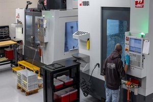
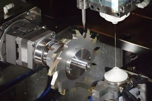
#5 CNC Milling
CNC milling is a machining process that utilizes computer-controlled machines to remove material from a workpiece using rotary cutters. It allows for the creation of complex shapes and patterns with high precision. CNC milling machines come in various types, including:
- Vertical Milling Machines: Used for face milling, end milling, drilling, and tapping. Suitable for small and large-scale production.
- Horizontal Milling Machines: Ideal for heavy-duty cutting tasks such as grooving, slotting, and contouring.
- 5-Axis Milling Machines: Capable of intricate and complex machining operations on multiple sides of the workpiece simultaneously.
- CNC Mill-Turn Machines: Combine the functionalities of milling and turning in a single unit, enabling efficient production of complex parts.
CNC milling machines provide versatility, precision, and efficiency in manufacturing intricate components across industries.
#6 CNC Grinding
CNC grinding is a machining process that utilizes computer-controlled machines to remove material from a workpiece using abrasive wheels. It plays a significant role in precision machining, achieving tight tolerances and superior surface finishes. CNC grinding is crucial for industries requiring precise component dimensions, such as automotive, aerospace, and tool manufacturing.
Various types of CNC grinding techniques are employed based on specific requirements:
- Surface Grinding: Used to create flat surfaces on the workpiece, surface grinding utilizes rotating abrasive wheels.
- Cylindrical Grinding: In cylindrical grinding, the workpiece rotates while the grinding wheel removes material to achieve cylindrical shapes.
- Centerless Grinding: This technique involves grinding the outer diameter of cylindrical workpieces without using a center support.
- Internal Grinding: Internal grinding focuses on creating precise internal bores or holes using a small-diameter grinding wheel.
- Tool and Cutter Grinding: Tool and cutter grinding is employed for manufacturing and resharpening cutting tools like drills and end mills.
A wide range of materials can be ground using CNC grinding, including metals, ceramics, composites, and more. The choice of grinding technique and material depends on the desired outcome and the specific application requirements.
CNC grinding delivers exceptional precision and surface quality, making it indispensable in various industries. It enables manufacturers to achieve tight tolerances and produce components with superior performance characteristics.
#7 G-Code
Code is a programming language used to control CNC machines. It consists of a series of commands that instruct the machine on how to move, position, and perform various operations. G-Code is essential in CNC machining as it allows manufacturers to precisely control the movements of the cutting tool and workpiece, ensuring accurate and consistent machining processes. It serves as the bridge between the design intent and the actual execution on the CNC machine.
#8 Tolerance
Tolerance refers to the acceptable deviation or variation in dimensions, measurements, or characteristics of a machined part or component. It represents the allowable limit for how much a feature can deviate from its intended design specification. Tolerance is a critical aspect of CNC machining as it ensures that parts are manufactured within acceptable limits and meet the required design specifications.
Tolerance is typically expressed as a numerical value and is denoted with a plus (+) and minus (-) sign to indicate the acceptable range. For example, if a hole diameter has a tolerance of ±0.02 mm, it means that the actual diameter of the hole can deviate by up to 0.02 mm from the specified dimension in both the positive and negative directions.
Tolerances are determined based on various factors, including the intended function of the part, the machining processes involved, the material being used, and the desired level of precision. Different features on a part may have different tolerance requirements based on their importance and functional requirements.
Tolerance is essential in CNC machining because it ensures that parts fit together properly, function as intended, and meet quality standards. It allows for a certain level of variation that is considered acceptable while maintaining the overall functionality and integrity of the part. By setting specific tolerances, manufacturers can achieve the desired level of precision and ensure the interchangeability and compatibility of components.
For example, consider a mechanical assembly that includes multiple parts. If the tolerance for the mating features, such as holes and shafts, is too tight, it may lead to interference or binding issues. On the other hand, if the tolerance is too loose, it may result in excessive play or misalignment. By specifying appropriate tolerances, manufacturers can ensure that the parts fit together correctly, allowing for smooth assembly and optimal functionality of the final product.
#9 Depth Per Pass
The depth per pass refers to the amount of material that is removed by the cutting tool in a single cutting operation. It determines the depth of the cut made by the tool into the workpiece during each pass. The depth per pass is an important parameter that affects the efficiency, accuracy, and surface finish of the machining process.
The depth per pass is typically specified in terms of a distance or a percentage of the tool diameter. For example, if the depth per pass is set to 0.5 mm, it means that the cutting tool will remove 0.5 mm of material from the workpiece during each pass. Alternatively, if the depth per pass is specified as 25% of the tool diameter, and the tool diameter is 10 mm, then the depth per pass would be 2.5 mm.
The selection of the appropriate depth per pass depends on various factors, including the material being machined, the cutting tool’s capabilities, the rigidity of the machine, and the desired surface finish. Setting the depth per pass too high may result in excessive cutting forces, tool deflection, poor surface finish, and even tool breakage. On the other hand, setting the depth per pass too low can lead to longer machining times and reduced productivity.
To illustrate the concept, let’s consider a CNC milling operation on a workpiece. The machining program specifies a depth per pass of 1 mm. The cutting tool engages with the workpiece and removes 1 mm of material during each pass. As the tool moves along the programmed tool path, it gradually removes material layer by layer until the desired depth is achieved. This incremental approach helps manage cutting forces, reduces the risk of tool damage, and improves surface finish.
It’s important to note that the depth per pass is typically determined through a balance between material removal rate, cutting tool capabilities, and the desired machining outcome. It is common for machinists to optimize the depth per pass based on the specific requirements of the machining operation, ensuring efficient material removal while maintaining the integrity and quality of the machined part.
#10 Feed Rate
Feed rate refers to the speed at which the cutting tool moves along the workpiece during a machining operation. It determines how quickly the tool advances or feeds into the material being machined. The feed rate is an important parameter that affects the efficiency, tool life, and surface finish of the machining process.
The feed rate is typically specified in units of distance per time, such as millimeters per minute (mm/min) or inches per minute (in/min). For example, if the feed rate is set to 100 mm/min, it means that the cutting tool will move at a speed of 100 millimeters per minute along the workpiece.
The selection of the appropriate feed rate depends on various factors, including the material being machined, the cutting tool’s capabilities, the rigidity of the machine, and the desired machining outcome. Setting the feed rate too high may result in excessive cutting forces, tool wear, poor surface finish, and even damage to the workpiece or machine. On the other hand, setting the feed rate too low can lead to longer machining times and reduced productivity.
To illustrate the concept, let’s consider a CNC milling operation on a workpiece. The machining program specifies a feed rate of 500 mm/min. The cutting tool moves along the programmed tool path at a speed of 500 millimeters per minute, removing material as it advances. This feed rate determines how quickly the tool engages with the workpiece and progresses through the material.
Machinists adjust the feed rate based on factors such as the material properties, desired chip load, cutting tool capabilities, and the desired surface finish. Higher feed rates can lead to increased material removal rates and shorter machining times, but they must be carefully balanced with the cutting tool’s capabilities and the machine’s rigidity to ensure optimal results.
It’s worth noting that the feed rate can vary during different stages of the machining operation. For instance, roughing passes may utilize a higher feed rate for efficient material removal, while finishing passes may use a lower feed rate to achieve a smoother surface finish. Machinists often optimize the feed rate based on the specific requirements of the machining operation, striking a balance between productivity and the quality of the machined part.
#11 Jig
A jig is a specialized tool or device that is used to hold and support a workpiece during the machining process. It is designed to ensure precise positioning, stability, and repeatability of the workpiece, allowing for accurate and consistent machining operations. Jigs play a crucial role in increasing productivity, maintaining quality, and reducing setup times in CNC machining.
A jig is typically custom-made to fit a specific workpiece or a group of similar workpieces. It securely holds the workpiece in place and provides a reference surface or guide for the cutting tool to follow. Jigs are often designed with clamps, fixtures, or other mechanisms to firmly secure the workpiece, preventing movement or vibration during machining.
The primary purpose of using a jig in CNC machining is to enhance accuracy and repeatability. By precisely positioning the workpiece, jigs enable consistent machining results and minimize errors. They ensure that features and dimensions are machined in the correct locations, maintaining the required tolerances and ensuring proper fit and functionality of the final product.
Jigs are widely used in various CNC machining operations, including milling, drilling, tapping, and profiling. They are employed in industries such as aerospace, automotive, electronics, and general manufacturing, where precise and repetitive machining operations are required.
One example of a jig is a drill jig used for drilling holes in a workpiece. The drill jig securely holds the workpiece in place and provides precise guides for positioning the drill bit. This ensures that the holes are drilled accurately at the desired locations with consistent dimensions.
By using jigs, CNC machinists can streamline the machining process, reduce setup times, and improve overall efficiency. Jigs allow for batch or mass production by facilitating the rapid setup and removal of workpieces, ensuring consistent results from one part to the next.
#12 Spindle
A spindle refers to a crucial component that holds and drives the cutting tool during the machining process. It plays a vital role in the overall functionality of a CNC machine. The spindle’s primary function is to rotate the cutting tool at high speeds, allowing it to remove material from the workpiece with precision.
The spindle is an essential element discussed in detail in our previous article 12 Essential Components of a CNC Machine Every Beginner Should Know. This article provides valuable insights into the various components that make up a CNC machine and their significance in the machining process. To learn more about the importance of the spindle and its role in CNC machining, we recommend referring to that article.
The selection of the appropriate spindle for a specific machining operation is crucial. Factors such as the material being machined, the cutting tool requirements, and the desired surface finish need to be considered. CNC machines are designed with different spindle options to accommodate various applications and requirements. Understanding the functionality and capabilities of the spindle is essential for beginners in the CNC machining field.
#13 Deburring
Deburring refers to the process of removing burrs or sharp edges from a machined part or component. Burrs are unwanted protrusions of material that can occur during the machining process, particularly in operations such as milling, drilling, or turning. Deburring is an essential step in the finishing process to ensure the smoothness, safety, and functionality of the final product.
During CNC machining, cutting tools remove material from the workpiece, leaving behind small raised edges or burrs along the machined surfaces. These burrs can be sharp, jagged, or uneven, posing potential hazards, affecting the part’s fit or function, or compromising the aesthetics of the finished product. Deburring aims to eliminate these burrs, resulting in a clean, smooth, and polished surface.
Deburring can be performed using various methods and tools, depending on the nature of the workpiece and the severity of the burrs. Common deburring techniques include manual deburring using hand tools, such as files or abrasive pads, as well as automated methods like tumbling, vibratory finishing, or sandblasting.
Manual deburring involves carefully removing burrs and sharp edges by hand using specialized tools. This method provides greater control and precision, making it suitable for intricate or delicate parts. Automated deburring methods, on the other hand, are often employed for high-volume production, where efficiency and consistency are crucial.
The choice of deburring method depends on factors such as the material being machined, the size and complexity of the part, the required level of surface finish, and the production volume. Deburring not only enhances the safety and usability of the machined part but also contributes to the overall quality and aesthetics of the final product.
Deburring is an important step in CNC machining and is often performed as part of the post-machining finishing process. By removing burrs and sharp edges, deburring improves the functionality, quality, and safety of the machined components, ensuring that they meet the desired specifications and requirements.
#14 Electrical Discharge Machining (EDM)
Electrical Discharge Machining (EDM) is a non-traditional machining process used to shape intricate parts in hard or difficult-to-machine materials. It involves controlled erosion using electrical sparks or discharges. EDM is popular in industries like aerospace and automotive for its ability to produce precise details and complex shapes. The process utilizes a dielectric fluid, CNC control, and two main types: wire EDM and sinker EDM. EDM is ideal for working with materials like hardened steel and titanium, enabling the creation of intricate molds, dies, and components with high precision. While slower than conventional methods, EDM is valued for its ability to machine complex 3D geometries and handle challenging materials.
#15 Surface Finish
Surface finish refers to the quality and texture of the surface produced after a machining operation. It describes the characteristics of the surface in terms of its smoothness, roughness, and overall appearance. Achieving the desired surface finish is crucial in CNC machining as it impacts the functionality, aesthetics, and performance of the final product. The surface finish can be influenced by factors such as cutting parameters, tool selection, machining techniques, and post-machining processes.
Conclusion
We have covered the essential terms in CNC machining, encompassing various aspects. Acquiring a solid understanding of these terms is vital for beginners entering the field of CNC machining.
As we wrap up, we encourage you to explore our article 5 Exciting Evolutionary Milestones in CNC Machining History to discover the remarkable advancements that have shaped the industry over time. By understanding the historical context and essential terms, you will gain a deeper appreciation for the evolution of CNC machining.
Other Articles You Might Enjoy
- Precision CNC Machining of Steel: High-Volume Production
Precision CNC Machining and High-Volume Production As an integral part of modern manufacturing processes, Precision Computer Numerical Control (CNC) machining brings about unmatched accuracy and consistency in the production of…
- Material Versatility in CNC Machining: From Titanium to Thermoplastics
Introduction to CNC Machining CNC machining stands as a cornerstone in the manufacturing sector, enabling the precise creation of parts and components. This process utilizes computer numerical control (CNC) to…
- Precision CNC Machining for High-Performance Industrial Machinery
Precision CNC Machining for High-Performance Industrial Machinery The process of Precision CNC (Computer Numerical Control) machining is at the core of manufacturing high-performance industrial machinery. This technique leverages a computer's…