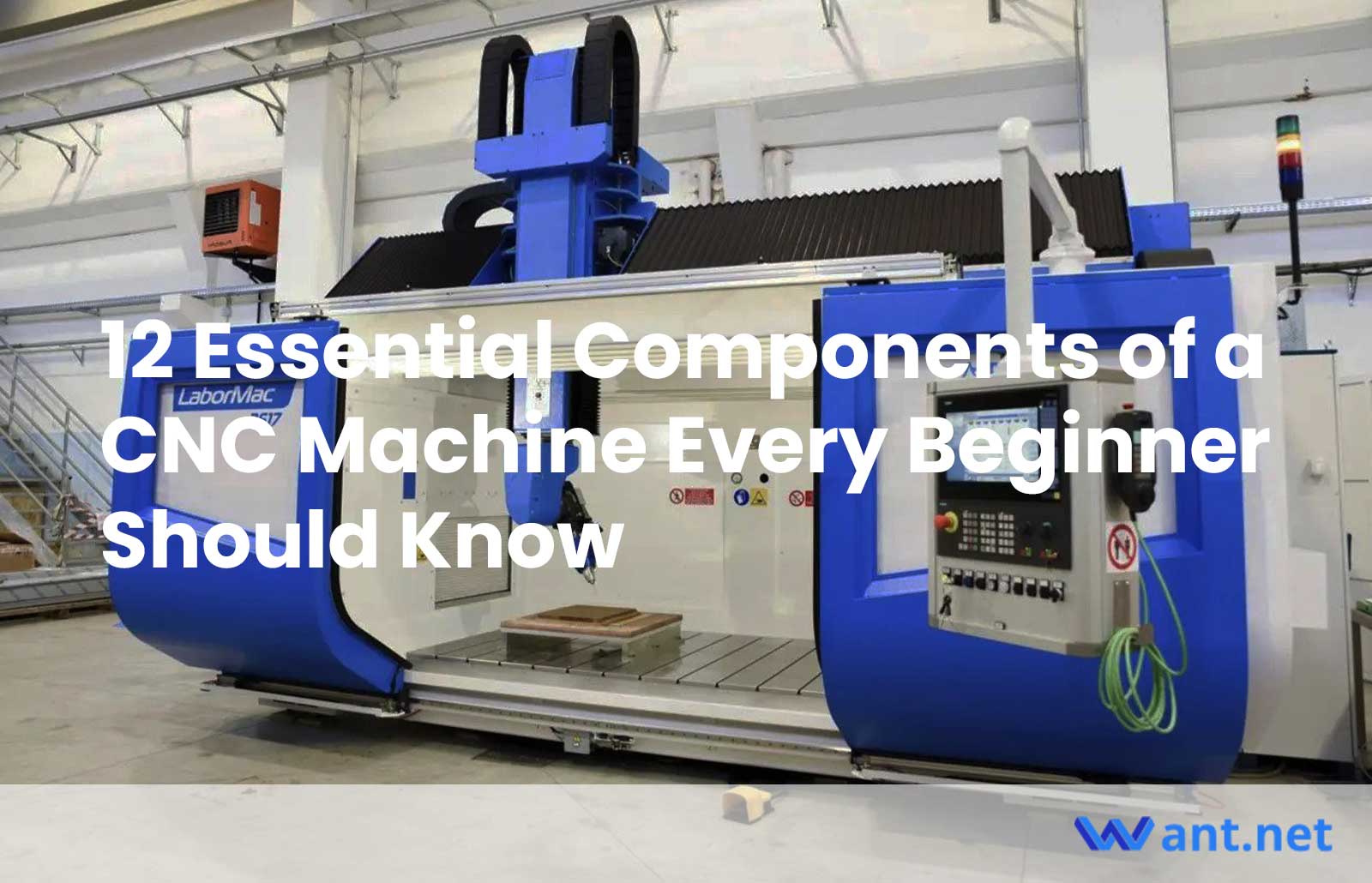
CNC machines, the unsung heroes of modern manufacturing, have revolutionized the way we create precision parts and intricate designs. For beginners embarking on their CNC journey, understanding the essential components of these marvelous machines is a crucial first step. These components, working in harmony, bring life to the computerized commands and transform raw materials into remarkable creations. In this article, we will explore the 12 fundamental components that every beginner should know, unveiling the inner workings that make CNC machines tick. So, fasten your seatbelts, engage your curiosity, and let’s embark on a captivating journey through the heart of CNC technology!
Control Panel and Controller
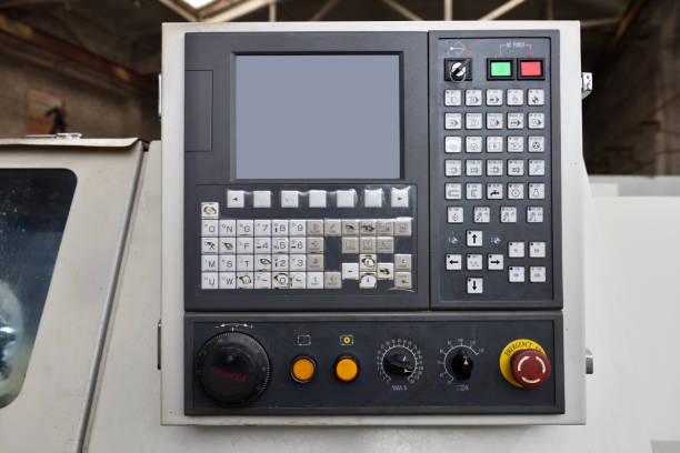
At the helm of every CNC machine lies the control panel, a user-friendly interface that allows operators to communicate with the machine. Much like a captain steering a ship, the control panel empowers users to input instructions and navigate through the machining process. It houses an array of buttons, knobs, and a display screen, providing a gateway to the machine’s capabilities. With the control panel, operators can specify parameters, select tools, and monitor the progress of their machining operations. It serves as the command center, bridging the gap between human intention and mechanical execution.
Working hand-in-hand with the control panel is the controller, the brilliant mind of the CNC machine. Like a fluent translator, the controller comprehends the instructions inputted through the control panel and translates them into electrical signals that the machine components can understand. It takes the operator’s desires and transforms them into precise movements and actions. Through a series of algorithms and calculations, the controller orchestrates the coordination of motors, spindles, and other vital components, ensuring an accurate and efficient machining process. It serves as the machine’s brain, executing the operator’s commands with remarkable precision.
For beginners venturing into the world of CNC machining, becoming well-acquainted with the control panel and controller interface is of paramount importance. Just as learning a new language empowers communication, understanding the control panel allows operators to navigate the CNC machine’s functionalities effectively. By familiarizing oneself with the buttons, knobs, and display, beginners gain the confidence to interact with the machine, unlock its full potential, and troubleshoot any issues that may arise. Mastery of the control panel and controller interface empowers operators to translate their creative visions into tangible results, unleashing the true capabilities of CNC technology.
To gain a comprehensive understanding of the fascinating journey CNC machining has undergone, it’s worth exploring the article on 5 Exciting Evolutionary Milestones in CNC Machining History This piece delves into the transformative advancements that have shaped the industry, providing insights into how CNC technology has evolved over time.
Motors

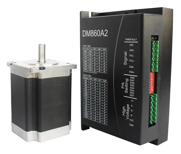
In the realm of CNC machines, two types of motors reign supreme: stepper motors and servo motors. Stepper motors are like precise clockwork, dividing movement into discrete steps. They excel in applications that require accurate positioning and repeatability. With their defined steps, stepper motors provide excellent control over movement, making them ideal for tasks such as 2D cutting and engraving.
On the other hand, servo motors are more akin to adaptable athletes, continuously adjusting to achieve optimal performance. They rely on feedback mechanisms to monitor and adjust their position, speed, and torque. This adaptability allows servo motors to handle complex operations that demand real-time adjustments, such as 3D milling or intricate contouring. Servo motors offer higher speeds, smoother motion, and greater power, making them the go-to choice for dynamic machining operations.
Motors play a pivotal role in propelling the various axes of movement in a CNC machine. Each axis—typically X, Y, and Z—represents a distinct direction in which the cutting tool or workpiece can move. Stepper motors and servo motors are responsible for driving these axes, enabling precise control and movement.
As the controller sends electrical signals to the motors, they convert this energy into mechanical motion. The motors spin lead screws, drive belts, or other transmission mechanisms, propelling the axes along their designated paths. This coordinated movement allows the cutting tool to traverse the workpiece with exceptional accuracy, translating digital designs into tangible objects.
Motor selection is a critical consideration when embarking on CNC machining projects. The choice of motor depends on the specific application’s requirements and desired outcomes. Stepper motors excel in tasks that demand precise positioning, such as engraving or PCB milling, where accuracy is paramount. Their affordability and simplicity make them popular among beginners.
Conversely, servo motors shine in applications that necessitate dynamic adjustments and higher speeds, such as complex 3D milling or rapid prototyping. They offer superior responsiveness and can handle varying loads and speeds with ease. However, servo motors often come at a higher cost and require more advanced tuning and control.
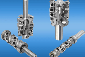
Spindle
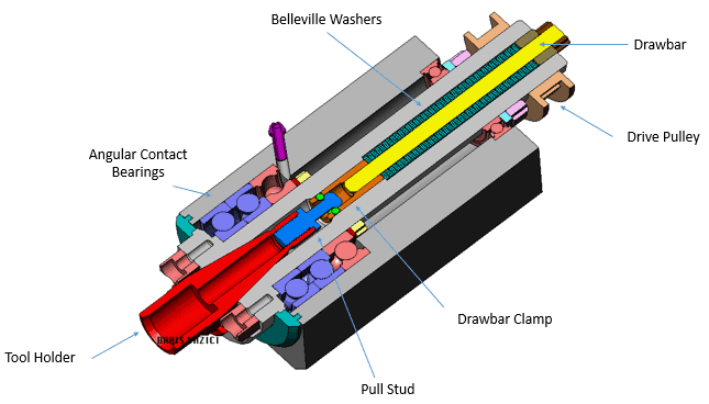
The spindle is a vital component of a CNC machine, serving as the powerhouse that holds and rotates the cutting tool. Similar to a conductor leading an orchestra, the spindle orchestrates the symphony of machining operations. Its primary function is to provide the rotational motion necessary for cutting, drilling, or shaping the workpiece.
Situated at the heart of the machine, the spindle ensures that the cutting tool spins at high speeds, allowing it to penetrate the workpiece with precision and efficiency. The spindle’s robust construction and precise bearings enable it to handle the demanding forces and vibrations generated during machining, ensuring stability and accuracy.
CNC machines employ two primary types of spindles: motorized spindles and separate motor-driven spindles.
A motorized spindle combines the spindle itself with an integral motor. This integrated design offers compactness and simplicity. The motorized spindle eliminates the need for a separate motor and provides direct power transmission to the cutting tool. This configuration reduces vibration and increases overall machining accuracy.
In contrast, a separate motor-driven spindle utilizes a dedicated motor that drives the spindle. This setup allows for more flexibility in motor selection and provides better control over speed and torque. The separate motor-driven spindle offers higher power output and allows for customization based on specific machining requirements.
Spindle speed plays a crucial role in CNC machining. The rotational speed of the spindle determines the cutting tool’s surface speed, affecting the quality of the machined surface and the efficiency of the operation. Different materials and cutting tools require specific spindle speeds to achieve optimal results. Higher speeds are typically used for cutting softer materials, while lower speeds are suitable for tougher materials.
Tool compatibility is another crucial consideration related to the spindle. The spindle must be compatible with the cutting tools used for various machining operations. Factors such as tool shank size, tool holding mechanism (such as collets or tool holders), and spindle taper must align to ensure a secure and precise connection. Incorrect tool compatibility can lead to poor performance, tool slippage, or even damage to the machine or workpiece.
Tool Changer
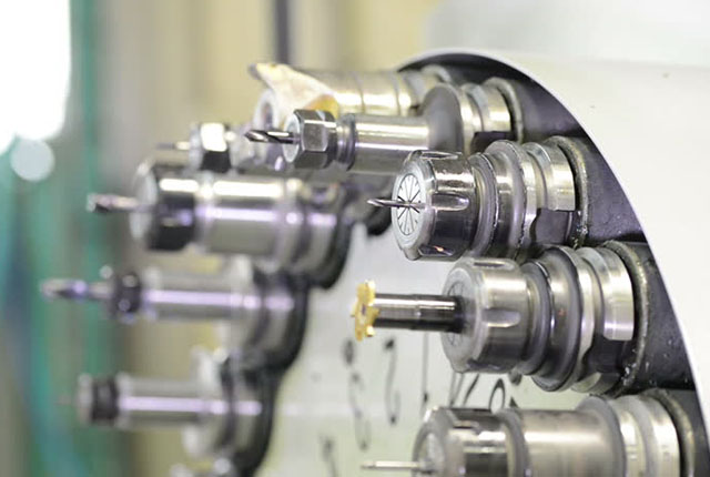
In the world of CNC machining, time is of the essence. Tool changers, a marvel of automation, have revolutionized the machining process by eliminating the need for manual tool swapping. Tool changers are mechanisms integrated into CNC machines that enable rapid and seamless interchangeability of cutting tools during machining operations. They bring efficiency and convenience to the workflow, allowing operators to effortlessly switch between different tools to accommodate diverse machining requirements.
The implementation of automated tool changers offers a multitude of advantages for CNC machining:
- Enhanced Efficiency: With manual tool changes, operators would need to halt the machining process, manually remove and install new tools, and reconfigure tool offsets. Automated tool changers streamline this process, reducing downtime and maximizing productivity. The machine can automatically swap tools within seconds, allowing uninterrupted machining and minimizing idle time.
- Increased Versatility: Automated tool changers enable CNC machines to tackle complex machining tasks that require multiple tools. Operators can easily program tool change sequences, allowing the machine to automatically select and install the appropriate tool for each specific operation. This versatility expands the range of machining possibilities, from intricate milling operations to multi-tool turning operations.
- Improved Accuracy: Tool changers ensure consistent tool positioning and alignment, reducing the chance of human error when manually changing tools. This consistent tool placement enhances machining accuracy, resulting in precise and reliable results.
- Tool Storage and Organization: CNC machines equipped with tool changers often incorporate tool storage magazines or carousels. These storage systems provide a centralized location for storing a variety of tools. Operators can conveniently store and retrieve tools from the magazine as needed, keeping the workspace organized and reducing the risk of misplaced or damaged tools.
While automated tool changers offer significant benefits, operators should consider a few factors when working with machines equipped with this feature:
- Tool Change Time: Despite the speed of automated tool changers, there is still a brief time required for the tool change process. Operators should consider the impact of tool change time on the overall machining cycle and plan accordingly to optimize efficiency.
- Tool Compatibility: Tool changers require compatible tool designs, such as standardized shank sizes and tool holding mechanisms. Operators should ensure that the tools they intend to use are compatible with the machine’s tool changer system to avoid compatibility issues.
- Maintenance and Calibration: Tool changers, like any mechanical system, require regular maintenance and calibration to ensure smooth operation. Operators should follow manufacturer guidelines for maintenance tasks such as lubrication, inspection, and calibration to maintain the reliability and accuracy of the tool changer system.
By understanding the advantages of automated tool changing and considering relevant factors, operators can harness the power of tool changers to improve efficiency, versatility, and machining precision in their CNC operations.
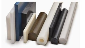
Bed/Table
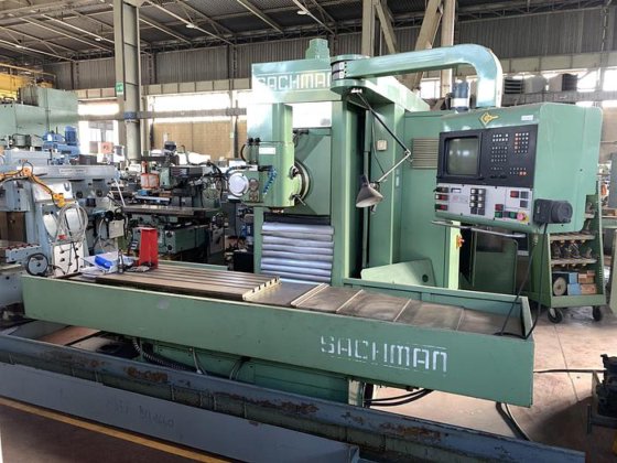
In a CNC machine, the bed or table serves as the foundation and workpiece surface. It provides a stable and rigid platform on which the workpiece is securely held during machining operations. The bed or table is typically made of a durable material like cast iron or steel, chosen for its strength and resistance to deformation under the cutting forces exerted during machining.
The workpiece is positioned and clamped onto the bed or table, ensuring it remains stationary while the cutting tool moves in various directions to shape and transform the material. The bed or table’s flat and level surface is essential for achieving precise and accurate machining results.
The bed or table of a CNC machine can move along different axes, usually denoted as X, Y, and Z, to position the workpiece accurately relative to the cutting tool. These axes correspond to the horizontal (X and Y) and vertical (Z) directions of movement.
The X-axis represents the horizontal movement from left to right or vice versa, allowing the workpiece to be positioned along the machine’s width. The Y-axis represents the horizontal movement from front to back or back to front, enabling positioning along the machine’s length. The Z-axis represents the vertical movement up or down, controlling the depth of the cutting tool’s penetration into the workpiece.
The coordinated movement along these axes allows the cutting tool to precisely follow the programmed toolpath, executing intricate shapes, contours, holes, and profiles with exceptional accuracy.
The stability and accuracy of the bed or table are critical factors in achieving successful machining outcomes. The bed must remain rigid and immovable during cutting operations to prevent unwanted vibrations or flexing that could compromise the accuracy of the workpiece.
Bed stability is crucial to minimize vibrations caused by cutting forces, ensuring the cutting tool remains on the desired toolpath. Vibrations can lead to poor surface finish, dimensional inaccuracies, and tool wear. A stable bed helps maintain consistent cutting forces, resulting in improved machining quality and prolonged tool life.
Additionally, the bed or table must provide accurate positioning along the X, Y, and Z axes. Any inaccuracies or deviations in the movement can lead to errors in the machined part’s dimensions, shape, or alignment. Precise positioning is particularly important for machining operations that require tight tolerances or complex geometries.
Therefore, maintaining the stability and accuracy of the bed or table through proper maintenance and alignment procedures is crucial. Regular inspection, leveling, and calibration ensure that the bed remains in optimal condition, providing a solid foundation for successful and precise machining operations.
Guides and Ways
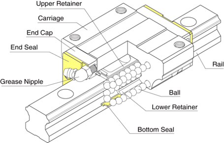
Guides and ways, or Guideways are essential components in CNC machines that provide stability, support, and precise movement for the various axes. They ensure smooth and controlled motion, allowing the cutting tool or workpiece to move accurately and reliably during machining operations.
The guides and ways consist of linear bearings or sliding surfaces that guide the motion of the machine components along the X, Y, and Z axes. These components reduce friction, absorb forces, and maintain alignment, enabling precise positioning and maintaining the integrity of the machine’s mechanical structure.
There are several types of guides and ways commonly used in CNC machines:
- Linear Guides: Linear guides, also known as linear bearings, use rolling elements such as balls or rollers that move along tracks. They provide low friction and high rigidity, allowing for smooth and accurate linear motion.
- Dovetail Slides: Dovetail slides employ a dovetail-shaped groove and corresponding matching surface to provide stability and resistance to sideways forces. They are commonly used for heavy-duty applications that require high load-carrying capacity and rigidity.
- Box Ways: Box ways, or box slides, utilize surfaces that slide within each other. They offer excellent rigidity and vibration damping, making them suitable for heavy-duty machining where high cutting forces are involved.
- Rack and Pinion: Rack and pinion systems use a toothed rack (a straight gear-like bar) and a pinion (a gear) to convert rotary motion into linear motion. They are often employed for rapid and precise movement of machine components, such as in CNC routers or plasma cutters.
The quality and condition of guides and ways significantly impact the precision and longevity of a CNC machine. High-quality guides and ways provide smoother and more accurate movement, minimizing vibrations, backlash, and play. This directly translates into improved machining precision, surface finish, and dimensional accuracy of the workpiece.
Additionally, well-maintained guides and ways reduce wear and friction, extending the lifespan of the machine. Regular cleaning, lubrication, and inspection of the guides ensure optimal performance and prevent premature deterioration.
On the other hand, poor-quality or worn-out guides and ways can lead to increased friction, inaccuracies, and reduced machine performance. Excessive play or backlash in the guides can cause positioning errors and compromise the quality of the machined parts. Neglecting maintenance of the guides may result in accelerated wear, leading to costly repairs or the need for component replacement.
Therefore, investing in high-quality guides and ways and implementing proper maintenance procedures is crucial for maintaining the precision, longevity, and overall performance of a CNC machine. Regular inspection, lubrication, and timely replacement of worn components are essential practices to ensure optimal machine operation.
Drive System
The drive system in a CNC machine plays a critical role in transmitting power from the motors to the different axes of movement. It converts the rotary motion of the motors into linear or rotational motion, enabling precise and controlled movement of the cutting tool or workpiece.
The drive system acts as the intermediary between the motors and the moving components, such as the leadscrews, belts, gears, or other transmission mechanisms. It transfers the rotational force generated by the motors to drive the linear or rotary motion required for machining operations.
The drive system comprises various components that work together to transmit power and facilitate movement:
- Belts and Pulleys: Belt and pulley systems utilize flexible belts and pulleys of different sizes to transfer motion between the motor and the axis. They provide smooth and precise movement, suitable for applications that require speed reduction or long-distance power transmission.
- Leadscrews and Nuts: Leadscrews, also known as power screws, are threaded rods that engage with nuts. As the leadscrew rotates, it causes linear motion by translating the rotational movement into axial movement. Leadscrews offer excellent accuracy and repeatability, making them suitable for applications that require precise positioning.
- Gears: Gears are toothed wheels that mesh with each other to transmit motion and power. They allow for speed reduction or amplification, as well as changing the direction of rotation. Gear systems are commonly used in CNC machines to transfer power and control the movement of the axes.
- Linear Actuators: Linear actuators are devices that convert rotary motion into linear motion. They often utilize mechanisms such as ball screws or rack and pinion systems to provide precise and controlled movement along the axes.
When selecting a drive system for a CNC machine, several considerations come into play:
- Speed and Precision: Different drive systems have varying speed and precision capabilities. Applications requiring high-speed machining may benefit from belt and pulley systems, while applications demanding high precision may require leadscrews or linear actuators.
- Load Capacity: The drive system must be able to handle the load of the moving components, including the cutting tool, workpiece, and associated forces. Choosing a drive system with the appropriate load capacity ensures stability and prevents excessive wear or failures.
- Backlash and Accuracy: Backlash, the amount of play or clearance in a drive system, affects the accuracy of the machine. Applications that require tight tolerances and minimal backlash may necessitate more precise drive systems, such as leadscrews or gears with low backlash.
- Maintenance and Durability: Consider the maintenance requirements and durability of the drive system components. Some systems may require regular lubrication, adjustment, or replacement of wear-prone components. Choosing a robust and reliable drive system minimizes downtime and maintenance costs.
By considering factors such as speed, precision, load capacity, backlash, and maintenance requirements, operators can choose the most appropriate drive system for their specific CNC machining applications, ensuring optimal performance and reliable operation.
Coolant System
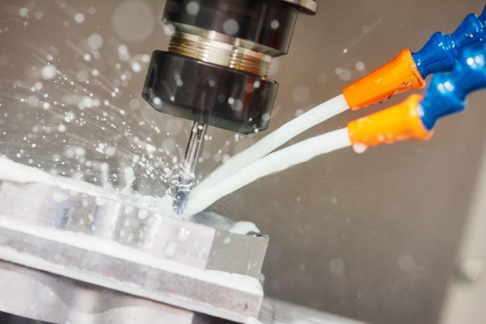
Coolant systems play a crucial role in CNC machines, offering a multitude of benefits that enhance machining performance and prolong tool life. These systems are designed to provide lubrication and cooling during machining operations, effectively managing heat generation and chip removal.
Coolant systems serve two primary functions: lubrication and cooling.
Lubrication: During machining, the cutting tool comes into contact with the workpiece, generating heat and friction. The coolant system supplies a lubricating fluid to reduce friction between the tool and the workpiece. This lubrication minimizes tool wear, reduces the chance of built-up edge formation, and prolongs tool life. It also helps prevent chip welding, where chips adhere to the cutting tool, leading to poor surface finish and reduced cutting efficiency.
Cooling: The intense heat generated during machining can adversely affect both the cutting tool and the workpiece. Coolant systems deliver a cooling fluid, typically a mixture of water and coolant additives, to dissipate heat. This cooling effect prevents thermal deformation of the workpiece, reduces thermal stress on the cutting tool, and helps maintain dimensional accuracy. Cooling also improves chip evacuation by reducing the chances of chip re-welding, chip accumulation, and chip-induced damage.
Coolant systems offer several key benefits for CNC machining:
- Prolonged Tool Life: Proper lubrication and cooling provided by coolant systems significantly extend the lifespan of cutting tools. Reduced friction and heat accumulation minimize tool wear, ensuring longer tool life and reducing the frequency of tool replacements. This leads to cost savings and improved machining efficiency.
- Surface Finish Improvement: Coolant systems contribute to better surface finish quality. Effective chip evacuation and reduced heat generation help prevent issues like surface roughness, built-up edge, and workpiece thermal distortion. The result is improved surface finish, dimensional accuracy, and overall part quality.
- Chip Management: Coolant systems assist in efficient chip evacuation. By cooling and lubricating the cutting zone, chips are effectively flushed away from the workpiece and tool, preventing chip recutting, built-up edge, and chip-induced tool wear. Proper chip management leads to smoother machining operations and reduces the risk of chip-related machining issues.
- Heat Dissipation: The cooling function of coolant systems helps dissipate the heat generated during machining. This prevents thermal expansion and distortion of the workpiece, ensuring dimensional accuracy and maintaining tight tolerances. It also reduces thermal stress on the cutting tool, preventing premature tool failure.
Sensors and Feedback Devices
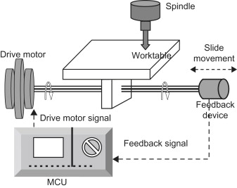
In the realm of CNC machines, sensors and feedback devices serve as the eyes and ears of the system, providing vital information to the controller. These components play a crucial role in monitoring and providing feedback on the position, status, and performance of various machine elements during machining operations.
Sensors are devices that detect and measure physical quantities such as position, speed, temperature, or pressure. They convert these physical properties into electrical signals that can be interpreted by the controller. Feedback devices, such as encoders and limit switches, are specific types of sensors commonly used in CNC machines to provide precise position and status information.
Encoders: Encoders are feedback devices that precisely measure the position and movement of machine components. They are commonly used to provide feedback on the position of the machine’s axes, tool, or workpiece. Encoders generate electrical signals proportional to the rotational or linear displacement, allowing the controller to accurately determine the position and adjust movements accordingly. By comparing the desired position with the actual position reported by the encoders, the controller can make real-time adjustments to ensure precise machining.
Limit Switches: Limit switches are sensors that detect the physical limits of movement along the machine’s axes. These switches are strategically placed to indicate the end or limit positions of the machine components. When a moving element reaches a specific position, the limit switch is triggered, sending a signal to the controller. This signal alerts the controller to stop the movement or change direction, preventing overtravel and potential collisions. Limit switches ensure safe operation and protect the machine and workpiece from damage.
Accurate position and status feedback are crucial for the successful operation of CNC machines. Here’s why:
- Position Control: Accurate position feedback from encoders allows the controller to precisely control the movement of the machine’s axes. By continuously comparing the desired position with the actual position reported by the encoders, the controller can make real-time adjustments to ensure the tool follows the programmed path with high precision. This accuracy is vital for achieving the desired machining results, maintaining dimensional accuracy, and avoiding errors or deviations.
- Safety and Collision Avoidance: Limit switches provide critical information about the position limits and prevent overtravel or collisions. By monitoring the position of machine components, the limit switches ensure that movements stay within safe boundaries and prevent damage to the machine, tool, or workpiece. This enhances operator safety and protects the machine from potential accidents or costly mishaps.
- Error Detection and Correction: Accurate feedback enables the detection of errors or malfunctions in real-time. If there is a discrepancy between the desired and actual positions, the controller can take corrective actions, such as issuing alarms, pausing the operation, or adjusting the machine parameters. Quick detection and correction of errors improve the reliability and accuracy of the machining process, minimizing the chances of producing defective parts.
Overall, accurate position and status feedback provided by sensors and feedback devices enable CNC machines to operate with precision, safety, and efficiency. The feedback loop between the machine components and the controller ensures that movements are controlled and monitored, resulting in high-quality machining and reliable performance.
Workholding Devices
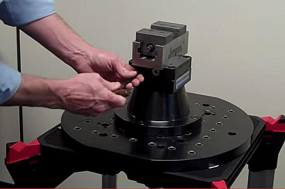
Workholding devices are essential components in CNC machines used to secure and immobilize the workpiece during machining operations. They ensure that the workpiece remains in a fixed position relative to the cutting tool, allowing for precise and accurate machining. Workholding devices play a significant role in achieving consistent results, minimizing vibrations, and preventing workpiece movement or distortion during cutting.
There are various types of workholding devices utilized in CNC machines, each designed for specific applications and workpiece configurations. Some commonly used workholding devices include:
Vises: Vises are versatile workholding devices with adjustable jaws that grip the workpiece. They are often used for securing smaller workpieces or parts that require multiple-sided machining. Vises offer flexibility, ease of use, and repeatability in clamping operations.
Clamps: Clamps are simple but effective devices used to hold the workpiece securely in place. They come in various designs, such as toggle clamps, C-clamps, or strap clamps. Clamps are particularly useful when machining irregularly shaped or larger workpieces that cannot be accommodated by other workholding devices.
Chucks: Chucks are commonly used in CNC lathes for securing cylindrical or round workpieces. They provide firm grip and concentricity, allowing for rotational machining operations. Chucks come in different types, including three-jaw chucks, four-jaw chucks, and collet chucks, providing versatility for different workpiece sizes and configurations.
Fixtures: Fixtures are specialized workholding devices designed for specific machining tasks or complex workpiece geometries. They are custom-made to hold the workpiece securely in a predetermined position, ensuring precise alignment and repeatability. Fixtures often incorporate clamps, locators, and other features to precisely position the workpiece for machining.
Safety Features
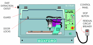
Safety features in CNC machines are designed to protect operators, prevent accidents, and ensure safe operation. These features are crucial in maintaining a secure working environment. CNC machines are equipped with various safety mechanisms and devices that prioritize operator safety and minimize potential hazards.
- Emergency Stop Buttons: CNC machines are equipped with prominently placed emergency stop buttons, often referred to as E-stops. Pressing the emergency stop button immediately halts all machine movements and shuts down the power to prevent any further operation. This feature is essential in emergency situations or when an immediate stop is required to ensure operator safety or prevent damage to the machine or workpiece.
- Protective Enclosures: CNC machines are often enclosed within protective enclosures or barriers. These enclosures serve multiple purposes, including preventing operators from coming into contact with moving machine components, reducing noise levels, containing flying debris or chips generated during machining, and providing a physical barrier to enhance safety.
- Interlocks: Interlocks are safety mechanisms that prevent specific actions or operations from occurring under unsafe conditions. They ensure that certain conditions are met before a machine can be operated. For example, the machine door may be equipped with an interlock that halts machine operation if the door is open, preventing accidental contact with moving components. Interlocks are designed to enforce safe practices and prevent potentially dangerous situations.
Conclusion
CNC machines are intricate systems comprised of various components that work harmoniously to transform digital designs into tangible objects. Familiarizing yourself with the components of a CNC machine is crucial, especially for beginners embarking on their CNC machining journey.
Knowing the purpose and functionality of each component enables you to make informed decisions, troubleshoot issues, and optimize your machining operations. It empowers you to harness the full potential of CNC technology and achieve accurate, efficient, and high-quality results.
As a beginner, take the time to familiarize yourself with the components. Explore their roles, functions, and how they interact with one another. Embrace the learning process, seek out resources, and ask questions. Building a strong foundation of knowledge about CNC machine components will lay the groundwork for your growth and success in CNC machining.
Remember, success in CNC machining is not solely dependent on mastering software or operating procedures. It is the combination of technical expertise, creativity, and a deep understanding of the machine’s components that unlocks the true potential of CNC technology.
So, embrace the challenge, dive into the world of CNC machining, and let your knowledge of CNC machine components be the compass that guides you towards achieving remarkable precision and craftsmanship. Happy machining!