Introduction: The Language of Innovation
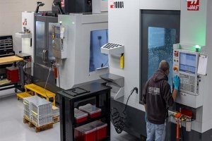
Engineering drawings are the backbone of every engineering marvel, from towering skyscrapers to intricate medical devices. As a mechanical engineer with over a decade in CNC machining, I’ve seen firsthand how these engineering drawings transform ideas into reality using a precise language of lines, symbols, and dimensions. In my experience, a well-crafted engineering drawing is not just a technical document but a roadmap that guides CNC machining processes, ensuring every cut and contour is executed flawlessly. Today, as digital tools reshape design, engineering drawings remain critical, especially in CNC machining where precision is paramount. Misinterpreting these drawings can lead to scrapped parts or costly delays in the machine shop. This guide dives into the anatomy of engineering drawings, their evolution, and their future, blending my insights from years on the shop floor with a look at cutting-edge technologies like Model-Based Definition (MBD), Augmented Reality (AR), and Artificial Intelligence (AI).
The Universal Language of Engineering Drawings
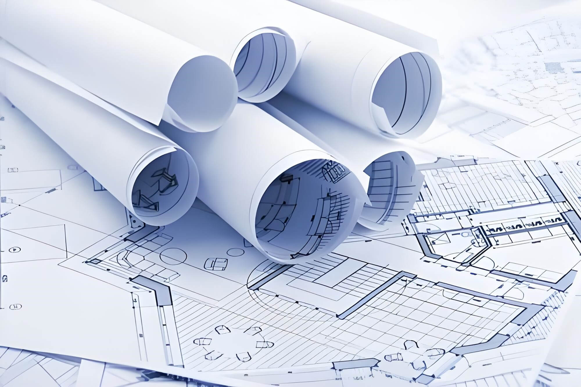
Engineering drawings are the universal bridge between a designer’s vision and the physical world, particularly in CNC machining where they dictate every toolpath. I recall a project where a vague engineering drawing led to a batch of mis-machined parts, costing thousands in rework. These drawings provide all the information needed to create, inspect, and assemble components with precision. They are indispensable in CNC machining, where tight tolerances and material specifications are non-negotiable. Engineering drawings serve four key roles: they communicate design intent clearly to machinists, guide CNC programming and manufacturing, set quality control standards for inspection, and act as legally binding documents in contracts or patents. From my perspective, their ability to align designers, machinists, and inspectors makes engineering drawings the linchpin of successful CNC machining projects.
Deconstructing Engineering Drawings
Engineering drawings may seem daunting, but their structured conventions make them a universal tool, especially in CNC machining. The title block, typically in the bottom-right corner, is like the drawing’s ID card, listing part details, units, scale, and tolerances—crucial for setting up CNC machines accurately. I’ve often relied on the title block’s tolerance notes to adjust feeds and speeds on a CNC mill. A revision block tracks changes, ensuring traceability, while assembly engineering drawings include a Bill of Materials (BOM) to guide CNC-machined component integration. Lines in engineering drawings form a precise alphabet: visible lines show edges, hidden lines reveal concealed features, and center lines mark symmetry—vital for aligning CNC toolpaths. Orthographic views (front, top, right-side) translate 3D parts into 2D for CNC programming, with sectional views exposing internal features critical for machining complex geometries. Dimensions and tolerances, including Geometric Dimensioning & Tolerancing (GD&T), define exact requirements, ensuring CNC-machined parts meet specifications.
Table 1: Anatomy of Engineering Drawings
| Element | Appearance | Purpose | Why It’s Critical |
| Title Block | Rectangular box in corner | Provides metadata about the drawing and part | Ensures traceability and defines standards like units |
| Visible Line | Thick, solid line | Shows visible edges | Defines external shape |
| Hidden Line | Dashed line | Indicates hidden features | Prevents misinterpretation of internal geometry |
| Dimension | Number with arrowed lines | Defines size and location | Essential for manufacturing and inspection |
| Tolerance | ± symbol or range | Specifies allowable variation | Ensures parts fit and function correctly |
| Section View | Cross-hatched area | Reveals internal features | Clarifies complex internal geometry |
| BOM | List of parts and quantities | Lists assembly components | Supports procurement and assembly |
Types of Engineering Drawings
Engineering drawings vary by purpose, each tailored to specific needs, especially in CNC machining. Detail drawings provide precise instructions for machining a single component, critical for programming CNC lathes or mills. Assembly drawings show how CNC-machined parts fit together, often including BOMs to streamline production. I once worked on an assembly drawing that clarified a complex fixture setup, saving hours on the shop floor. Schematic drawings map system functions, like electrical circuits, less common in CNC machining but useful for integrated systems. Mechanical engineering drawings dominate CNC machining for parts and assemblies, while civil, architectural, and electrical drawings serve other fields. In large projects, design drawings outline intent, and shop drawings detail CNC machining processes, reviewed in an approval loop to ensure accuracy.
Reading Engineering Drawings
Reading engineering drawings is a skill honed through practice, especially for CNC machinists like me who rely on them daily. Start with the title block to understand part details and tolerances, then review notes and BOMs. Orthographic views help visualize the 3D shape, crucial for setting up CNC workpieces. I often project features across views to confirm machining sequences. Third-angle (US) and first-angle (Europe/Asia) projections can confuse—early in my career, I misread a first-angle drawing, nearly producing a mirrored part. A title block symbol clarifies the method, preventing such errors. Spatial intelligence, developed by modeling engineering drawings in CAD or tracing features, is essential for CNC programming. Studying ASME and ISO standards has helped me interpret engineering drawings accurately, ensuring machined parts meet design intent.
Global Standards for Engineering Drawings
Engineering drawings rely on global standards to ensure consistency, especially in CNC machining where precision is critical. Standards define rules for lines, symbols, and GD&T, eliminating ambiguity. ASME Y14.5 governs engineering drawings in the US, while ISO standards (e.g., ISO 8015) are global. I’ve worked with both, noticing ASME’s third-angle projection and broken-line dimensioning versus ISO’s first-angle and unbroken-line styles. ASME’s Envelope Principle ties size to form, impacting CNC tolerances, while ISO’s Independency Principle separates them. These standards ensure engineering drawings are universally understood, vital for global CNC machining projects.
Table 2: ASME vs. ISO Standards for Engineering Drawings
| Feature | ASME (US/ANSI) | ISO (International) |
| Projection Method | Third-Angle | First-Angle |
| Default Units | Inches (often) | Millimeters (mm) |
| Dimension Placement | In broken line | Above unbroken line |
| Sheet Sizes | ANSI A, B, C, D | ISO A4, A3, A2, A1 |
| Key Standard | ASME Y14.5 | ISO 8015 / ISO 1101 |
Evolution of Engineering Drawings
Engineering drawings have transformed from manual sketches to digital models, revolutionizing CNC machining. Hand-drawn drawings, once labor-intensive, gave way to CAD, enabling precise CNC toolpaths. I’ve used parametric modeling in CAD to tweak designs instantly, saving weeks compared to manual drafting. AutoCAD excels for 2D engineering drawings in architecture, SOLIDWORKS simplifies 3D mechanical designs for CNC machining, and CATIA handles complex aerospace parts. These tools have made engineering drawings more accessible, enhancing CNC machining accuracy.
Table 3: Modern CAD Software for Engineering Drawings
| Software | Primary Strength | Dominant Industries | Best For… |
| AutoCAD | 2D Drafting & Documentation | Architecture, Electrical | Floor plans, schematics, P&ID diagrams |
| SOLIDWORKS | 3D Parametric Mechanical Design | Manufacturing, Product Design | Consumer products, machined parts |
| CATIA | Complex Surface Modeling & Assemblies | Aerospace, Automotive | Car bodies, aircraft wings |
The Future of Engineering Drawings
Engineering drawings are evolving into 3D digital models, transforming CNC machining. Model-Based Definition (MBD) embeds all data into 3D models, eliminating 2D engineering drawings and streamlining CNC programming. I’ve seen MBD reduce errors by providing machinists with a single, clear data source. Augmented Reality (AR) overlays engineering drawings onto physical parts, aiding CNC setup and inspection. On one project, AR helped me verify a machined component against its digital model in real-time. AI-driven generative design creates optimized shapes for CNC machining, allowing me to select from thousands of options, accelerating innovation. These advancements make engineering drawings more powerful, enhancing CNC machining efficiency.
Conclusion: The Enduring Role of Engineering Drawings
From my years working with engineering drawings in CNC machining, I’ve learned they are more than technical documents—they’re the foundation of precision and innovation. As engineering drawings evolve into digital twins, their core principles of clarity and accuracy remain vital. Mastering engineering drawings ensures CNC-machined parts meet exacting standards, driving engineering excellence. I encourage you to explore CAD, MBD, and AR to harness the full potential of engineering drawings in your CNC machining projects.
FAQ:
1. What are engineering drawings, and why are they important in CNC machining?
Engineering drawings are standardized graphical documents that convey all necessary information to design, manufacture, and inspect a part. In my experience as a CNC machinist, these drawings are critical because they provide precise instructions for programming toolpaths, defining tolerances, and ensuring parts meet design intent. Without clear engineering drawings, CNC machining risks errors, scrapped parts, or costly rework.
2. How do I read engineering drawings for CNC machining?
Reading engineering drawings involves a systematic approach. Start with the title block to understand part details, units, and tolerances. Then, review notes and the Bill of Materials for assemblies. Use orthographic views to visualize the 3D shape, and check dimensions and GD&T for machining requirements. I’ve found that tracing features across views or modeling the drawing in CAD helps confirm CNC setups.
3. What’s the difference between first-angle and third-angle projection in engineering drawings?
First-angle projection (common in Europe/Asia) places views opposite their logical position, while third-angle (US/UK) aligns views intuitively, like top view above front view. A title block symbol clarifies the method. Early in my career, I nearly machined a mirrored part due to a misread first-angle drawing, highlighting why this distinction is critical for CNC machining.
4. How do ASME and ISO standards affect engineering drawings in CNC machining?
ASME Y14.5 (US) and ISO standards (global) define rules for engineering drawings, including projection, dimensioning, and tolerances. ASME uses third-angle projection and broken-line dimensioning, while ISO uses first-angle and unbroken lines. In CNC machining, these standards ensure drawings are universally understood, preventing errors in global projects. I rely on them to set precise CNC parameters.
5. How have engineering drawings evolved with CAD for CNC machining?
Traditional hand-drawn engineering drawings were time-consuming, but CAD software like AutoCAD, SOLIDWORKS, and CATIA revolutionized the process. Parametric modeling allows rapid design changes, directly impacting CNC toolpaths. I’ve used SOLIDWORKS to tweak engineering drawings in real-time, saving weeks compared to manual drafting and improving machining accuracy.
6. What is Model-Based Definition (MBD), and how does it impact CNC machining?
MBD embeds all design and manufacturing data into 3D models, eliminating 2D engineering drawings. In CNC machining, MBD streamlines programming by providing a single, error-free data source. I’ve seen MBD reduce setup errors on complex parts, as machinists access dimensions and tolerances directly from the model.
7. How does Augmented Reality (AR) enhance engineering drawings in CNC machining?
AR overlays engineering drawings onto physical parts, aiding setup, inspection, and assembly. On a recent project, I used AR to verify a CNC-machined component against its digital model in real-time, catching a discrepancy before it caused issues. AR makes engineering drawings more interactive, improving machining precision.
8. What role does AI play in engineering drawings for CNC machining?
AI-driven generative design creates optimized shapes based on constraints, redefining engineering drawings. For CNC machining, this means designs tailored for manufacturability. I’ve used AI outputs to select efficient part geometries, reducing material waste and machining time while maintaining strength.
Reference:
https://en.wikipedia.org/wiki/Engineering_drawing;
https://en.wikiversity.org/wiki/Engineering_Projects/Engineering_Drawing;
https://www.designingbuildings.co.uk/wiki/Engineering_drawing;
Other Articles You Might Enjoy
- How to Create Better Engineering Drawings that Machining Manufacturers Like
Engineering drawings can be used to communicate design intent for CNC-machined parts with tight tolerances or special requirements. Many of our customers are in the robotics, aerospace and automotive industries.…
- Breaking Down Design and Production Barriers: A Multidimensional Analysis of CNC Machining Part Drawings
CNC machining is a marvel of modern engineering, enabling the production of intricate parts with high precision. But behind every perfectly crafted piece lies the unsung hero of the process:…
- How To Prepare Your Drawings For CNC Milling
CNC machining service is one of the most well-known and common automated manufacturing processes. CNC machines make manufacturing processes more efficient and easier for individuals and companies. These machines are…
- Mechanical Drawing Annotation Methods and Common Issues and Requirements
In mechanical processing, drawing annotations play a crucial role. The first key point is that the true size of the part should be based on the dimensions indicated on the…
- How to prepare a technical drawing for CNC machining
Introduction to CNC Machining and the Importance of Technical Drawings Computer Numerical Control (CNC) machining has become a keystone in modern manufacturing due to its precision, high-speed performance, and automated…